HYBRID TRANSAXLE SYSTEM > DETAILS


CONSTRUCTION


  1. Hybrid Vehicle Transaxle Assembly

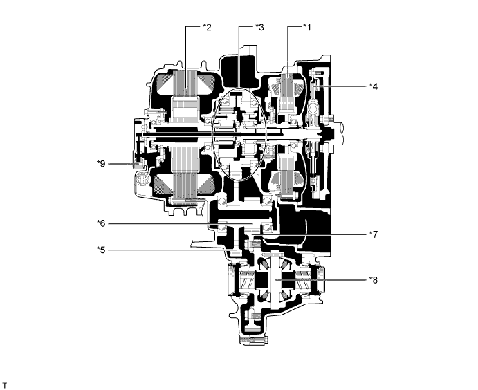
    1. This hybrid vehicle transaxle assembly consists primarily of MG1, MG2, a compound gear unit, a transaxle input damper assembly, a counter gear, a final gear, a differential gear unit and an oil pump.

    2. This hybrid vehicle transaxle assembly has a 3-shaft configuration. The compound gear unit, a transaxle input damper assembly, an oil pump, MG1 and MG2 are provided on the input shaft. The counter driven gear and the final drive gear are provided on the second shaft. The final driven gear and the differential gear unit are provided on the third shaft.


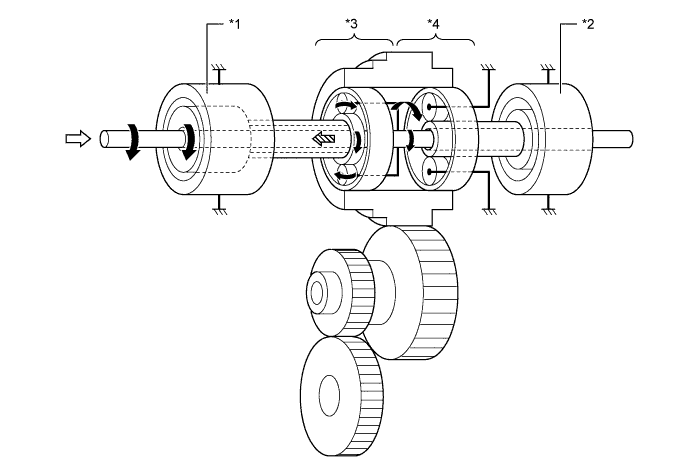
    3. The engine, MG1 and MG2 are mechanically joined via the compound gear unit.

      V100235E03


      Text in Illustration 
      *1
      MG1
      *2
      MG2
      *3
      Compound Gear Unit
      *4
      Transmission Input Damper Assembly
      *5
      Counter Driven Gear
      *6
      Final Drive Gear
      *7
      Final Driven Gear
      *8
      Differential Gear Unit
      *9
      Oil Pump
      -
      -


  2. Compound Gear Unit

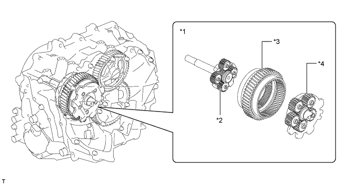
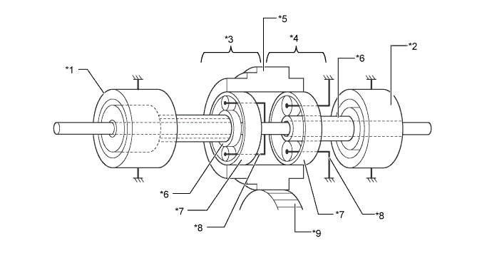
    1. The compound gear unit consists of the power split planetary gear unit and the motor speed reduction planetary gear unit. Each planetary ring gear is integrated with the compound gear. Furthermore, this compound gear is integrated with a counter drive gear and parking gear.

    2. The power split planetary gear unit splits the motive force of the engine two ways: one to drive the wheels, and the other to drive MG1, so that MG1 can function as a generator.


    3. The motor speed reduction planetary gear unit, whose purpose is to reduce MG2 speed, is used to enable the high-speed, high-output MG2 to adapt optimally to the compound gear.

      X101368E02


      Text in Illustration 
      *1
      Compound Gear Unit
      *2
      Power Split Planetary Gear Unit
      *3
      Counter Drive Gear (Compound Gear)
      *4
      Motor Speed Reduction Planetary Gear Unit


    4. The connection of the sun gear, ring gear and carrier of each planetary gear unit is as shown below.

      Item
      Connection
      Power Split Planetary Gear Unit
      Sun Gear
      MG1
      Ring Gear
      Compound Gear (To Wheels)
      Carrier
      Input Shaft (From Engine)
      Motor Speed Reduction Planetary Gear Unit
      Sun Gear
      MG2
      Ring Gear
      Compound Gear (To Wheels)
      Carrier
      Fixed

      X101369E03


      Text in Illustration 
      *1
      MG1
      *2
      MG2
      *3
      Power Split Planetary Gear Unit
      *4
      Motor Speed Reduction Planetary Gear Unit
      *5
      Counter Drive Gear
      *6
      Sun Gear
      *7
      Ring Gear
      *8
      Carrier
      *9
      Counter Driven Gear
      -
      -


  3. Transaxle Input Damper Assembly


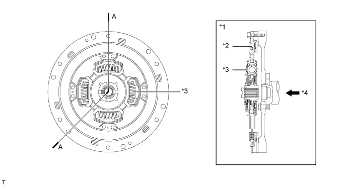
    1. A transaxle input damper assembly that consists of a coil spring with low-twist characteristics is used in order to absorb the torque fluctuation in the motive force of the engine. The torque limiter uses a dry-type, single-plate friction material. Through the use of these parts, a damper construction that excels in absorbing the vibrations of the engine motive force has been achieved.

      X101718E03


      Text in Illustration 
      *1
      A-A Cross Section
      *2
      Torque Limiter
      *3
      Coil Spring
      *4
      From Engine


  4. Oil Pump Mechanism


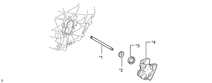
    1. The oil pump consists of the oil pump drive shaft, oil pump drive rotor, oil pump driven rotor and oil pump cover. The pump is driven by the engine via the input shaft and lubricates the gears.

      X101719E03


      Text in Illustration 
      *1
      Oil Pump Drive Shaft
      *2
      Oil Pump Drive Rotor
      *3
      Oil Pump Driven Rotor
      *4
      Oil Pump Cover


  5. Oil Sling Type Lubrication Mechanism

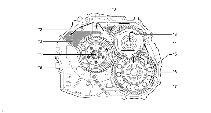
    1. This sling type lubrication mechanism uses the oil catch tanks and final driven gear, which sling the lubricant into the oil catch tanks. This construction minimizes the drive torque of the oil pump, which reduces the drive loss.


    2. The oil catch tanks are used in order to supply oil in a stable manner. The oil catch tanks temporarily store the oil that is slung up, and supply oil to the gears from there. Furthermore, oil holes are provided in the oil catch tanks in order to efficiently supply oil to MG1 and MG2.

      X101720E03


      Text in Illustration 
      *1
      Input Shaft
      *2
      Oil Hole
      *3
      Oil Catch Tank
      *4
      Second Shaft
      *5
      Final Gear Rotation Direction
      *6
      Third Shaft
      *7
      Final Driven Gear
      *8
      Counter Driven Gear
      *9
      Counter Drive Gear
      -
      -
      V100135
      Oil Flow
      -
      -


OPERATION


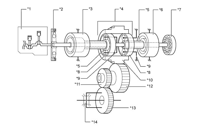
  1. Motive Force Transmission Path


    1. The motive force created by the engine and MG2 is transmitted by the counter drive gear of the compound gear unit, the counter driven gear, the final drive gear, and then the differential gear unit, in order to drive the front wheels.


      X101439E02


      Text in Illustration 
      *1
      Engine
      *2
      Transaxle Input Damper Assembly
      *3
      MG1
      *4
      Compound Gear Unit
      *5
      Sun Gear
      *6
      MG2
      *7
      Oil Pump
      *8
      Ring Gear
      *9
      Carrier
      *10
      Counter Drive Gear (Compound Gear)
      *11
      Final Drive Gear
      *12
      Counter Driven Gear
      *13
      Final Driven Gear
      *14
      Differential Gear Unit


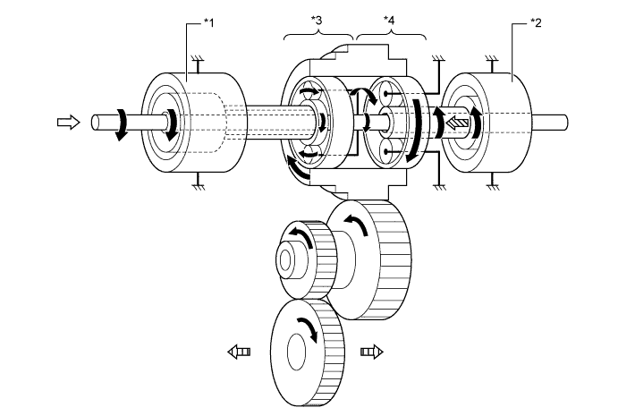
  2. Engine Motive Force and MG2 Motive Force Transmission Path


    1. The engine motive force, which is input by the carrier, is transmitted to the ring gear. The motive force of MG2 is transmitted to the ring gear via the motor speed reduction planetary gear unit. The sum of these two motive forces is transmitted by the compound gear in order to drive the wheels.


      X101783E03


      Text in Illustration 
      *1
      MG1
      *2
      MG2
      *3
      Power Split Planetary Gear Unit
      *4
      Motor Speed Reduction Planetary Gear Unit
      V100135
      Rotation Direction
      V100136
      From Engine
      V100137
      From MG2
      V100138
      To Wheel


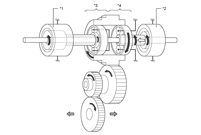
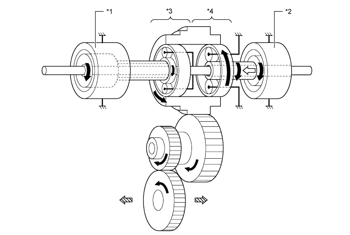
  3. MG2 Motive Force Transmission Path


    1. The motive force of MG2 is transmitted via the sun gear and is output to the ring gear in order to drive the wheels. The carrier of the motor speed reduction planetary gear unit is fixed. As a result, the motor speed reduction planetary gear unit reduces the speed of MG2, increasing torque in accordance with a set gear ratio. The rotation directions of forward and reverse become the opposite direction.


      X101784E02


      Text in Illustration (Driving Forward:) 
      *1
      MG1
      *2
      MG2
      *3
      Power Split Planetary Gear Unit
      *4
      Motor Speed Reduction Planetary Gear Unit
      V100135
      Rotation Direction
      V100136
      From MG2
      V100137
      To Wheel
      -
      -

      X101785E02


      Text in Illustration (Driving in Reverse:) 
      *1
      MG1
      *2
      MG2
      *3
      Power Split Planetary Gear Unit
      *4
      Motor Speed Reduction Planetary Gear Unit
      V100135
      Rotation Direction
      V100136
      From MG2
      V100137
      To Wheel
      -
      -


  4. Engine Motive Force Transmission Path


    1. The engine motive force, which is input by the carrier, is transmitted to the sun gear. Thus, motive force is transmitted in order to operate MG1 as a generator.


      X101786E02


      Text in Illustration 
      *1
      MG1
      *2
      MG2
      *3
      Power Split Planetary Gear Unit
      *4
      Motor Speed Reduction Planetary Gear Unit
      V100135
      Rotation Direction
      V100136
      From Engine
      V100137
      To MG1
      -
      -


  5. MG1 Motive Force Transmission Path


    1. The motive force of MG1 is transmitted via the sun gear and is output to the carrier. Thus, motive force is transmitted in order to start the engine.


      X101787E03


      Text in Illustration 
      *1
      MG1
      *2
      MG2
      *3
      Power Split Planetary Gear Unit
      *4
      Motor Speed Reduction Planetary Gear Unit
      V100135
      Rotation Direction
      V100136
      From MG1
      V100137
      To Engine
      -
      -