LEXUS PARKING ASSIST-SENSOR SYSTEM > DETAILS


FUNCTION OF MAIN COMPONENTS
*1: Models with navigation system
*2: Models with HDD navigation system
*3: Models with DVD navigation system

Component
Function
Ultrasonic Sensor (6)
Detects the distance between the vehicle and the obstacle.
Clearance Warning Buzzer
Sounds a buzzer to inform the driver according to the distance to the obstacle.
Combination Meter Assembly
Multi-information Display
  1. Displays the location of the obstacle and the approximate distance between the vehicle and the obstacle.
  2. Displays an indication of malfunction or freezing of an ultrasonic sensor to inform the driver.
LEXUS Parking Assist-sensor System Indicator Light
Illuminates to inform the driver when the system operation conditions are met.
Back Sonar or Clearance Sonar Switch Assembly
Operating this switch allows the operation of LEXUS parking assist-sensor system to be enabled or disabled
Clearance Warning ECU Assembly
  1. Judges the approximate distance between the vehicle and an obstacle based on signals from the ultrasonic sensors. Output signals are sent to the multi-information display and/or multi display.
  2. Sounds the clearance warning buzzer.
Multi Display*1
  1. Displays the location of the obstacle and the approximate distance between the vehicle and the obstacle.
  2. Displays an indication of malfunction or freezing of an ultrasonic sensor to inform the driver.
  3. The sound volume, distance required to sound the buzzer and distance required to trigger the display can be chosen on the setup screen for the LEXUS parking assist-sensor system.
Navigation Computer Sub-assembly*2
Transmits the setup signal for the LEXUS parking assist-sensor system to the clearance warning ECU assembly.
Display and Navigation Module Display*3
Power Management Control ECU
Transmits the shift position signal to the clearance warning ECU assembly.

OPERATING CONDITION
  1. The operating condition of each sensor differs according to its installed position as shown in the table below:

    Installation Position
    Operating Condition
    Front Corner
    1. Power switch is on (IG).
    2. System is activated
    3. R, N, D or B is selected using the shift lever.
    4. Vehicle speed is approximately 10 km/h (6 mph) or less.
    Rear Corner
    1. Power switch is on (IG).
    2. System is activated.
    3. Shift lever is in R.
    Rear Center
    1. Power switch is on (IG).
    2. System is activated.
    3. Shift lever is in R.


CONSTRUCTION


  1. Ultrasonic Sensor

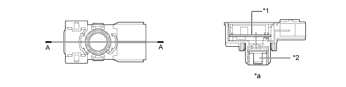
    1. The ultrasonic sensors consist of a microphone and a circuit portion that transmits and receives ultrasonic waves.


    2. The circuit portion is filled with silicone to prevent water from entering.


      Y109227E01


      Text in Illustration 
      *1
      Circuit Portion
      *2
      Microphone
      *a
      A-A Cross Section
      -
      -


OPERATION


  1. Clearance Warning Buzzer

    1. Depending on the detection distance and the detection area, the sound pattern of the clearance warning buzzer will vary.

      Detection Area
      Detection Distance
      Buzzer Sound Pattern On/Off Time (msec.)
      Corner
      Long
      50 +/- 5 cm to 37.5 +/- 5 cm (19.7 +/- 2 in. to 14.8 +/- 2.0 in.)
      150/150
      Middle
      37.5 +/- 5 cm to 25 +/- 5 cm (14.8 +/- 2 in. to 9.8 +/- 2.0 in.)
      75/75
      Short
      25 +/- 5 cm or less (9.8 +/- 2.0 in. or less)
      Continuous Sound/0
      Rear Center
      Longest
      150 +/- 15 cm to 60 +/- 10 cm (59.0 +/- 5.9 in. to 23.6 +/- 3.9 in.)
      150/650
      Long
      60 +/- 10 cm to 45 +/- 5 cm (23.6 +/- 3.9 in. to 17.7 +/- 2.0 in.)
      150/150
      Middle
      45 +/- 5 cm to 35 +/- 5 cm (17.7 +/- 2.0 in. to 13.8 +/- 2.0 in.)
      75/75
      Short
      35 +/- 5 cm or less (13.8 +/- 2.0 in. or less)
      Continuous Sound/0


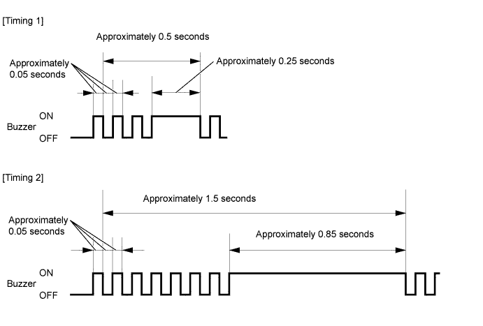
    2. When multiple sensors detect obstacles at the same time, the buzzer sounds as follows:

      Buzzer Sound Pattern ON/OFF Time (msec.) 
      Detection Distance
      Short
      Middle
      Long
      Longest
      Not detected
      Short
      Timing 1
      Timing 2
      Timing 2
      Timing 2
      Continuous Sound/0
      Middle
      Timing 2
      150/150
      150/150
      150/150
      150/150
      Long
      Timing 2
      150/150
      300/300
      300/300
      300/300
      Longest
      Timing 2
      150/150
      300/300
      800/800
      800/800
      Not detected
      Continuous Sound/0
      150/150
      300/300
      800/800
      None


      Y102524E04


  2. Multi-information Display

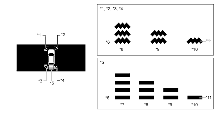
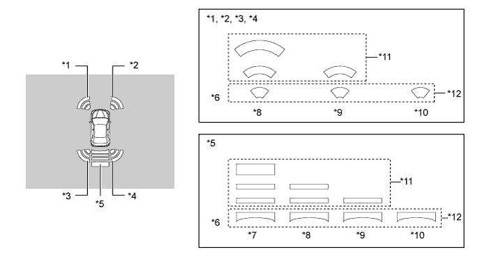
    1. The items displayed by the multi-information display are the location of the obstacle and the approximate distance between the vehicle and the obstacle.


    2. The number of lines shown on the display changes based on the actual distance and flashes when the distance is short.


      Y109452E01


      Text in Illustration 
      *1
      Front Corner LH
      *2
      Front Corner RH
      *3
      Rear Corner LH
      *4
      Rear Corner RH
      *5
      Rear Center
      *6
      Distance
      *7
      Longest
      *8
      Long
      *9
      Middle
      *10
      Short
      *11
      Flashes
      -
      -


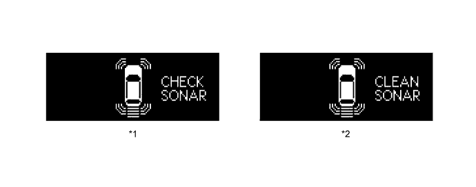
    3. The items displayed by the multi-information display are warning messages relating to sensor malfunction, sensor freezing, or presence of dirt on the sensor.


      Y109453E01


      Text in Illustration 
      *1
      Malfunctioning
      *2
      Frozen/Dirty


  3. Center Instrument Cluster Finish Panel Assembly (Multi-display)

    1. The items displayed by the multi display are the location of the obstacle and the approximate distance between the vehicle and the obstacle, warning messages relating to sensor malfunction, sensor freezing, or presence of dirt on the sensor.


    2. The distance is displayed by the number of lines and color based on the actual distance. The display usually illuminates in yellow. When the distance is short, it illuminates in red.


      Y103368E01


      Text in Illustration 
      *1
      Front Corner LH
      *2
      Front Corner RH
      *3
      Rear Corner LH
      *4
      Rear Corner RH
      *5
      Rear Center
      *6
      Distance
      *7
      Longest
      *8
      Long
      *9
      Middle
      *10
      Short
      *11
      Yellow
      *12
      Red

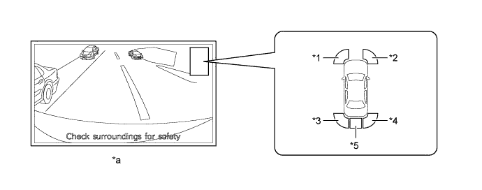
    3. If an obstacle is detected when the monitor system is activated, the approximate distance between the vehicle and the obstacle is displayed on the center instrument cluster finish panel assembly (multi-display).


    4. The distance is displayed by color based on the actual distance to the obstacle. When an obstacle is detected at the long or middle distance, the indicator is yellow. The color changes from yellow to red when the distance becomes short.


      Y109228E01


      Text in Illustration 
      *1
      Front Corner LH
      *2
      Front Corner RH
      *3
      Rear Corner LH
      *4
      Rear Corner RH
      *5
      Rear Center
      -
      -
      *a
      Rear View Monitor System Display
      -
      -


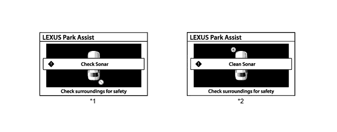
    5. The items displayed by the center instrument cluster finish panel assembly (multi-display) are warning messages relating to sensor malfunction, sensor freezing, or presence of dirt on the sensor.


      Y102528E05


      Text in Illustration 
      *1
      Malfunctioning
      *2
      Frozen/Dirty


    6. The display timing and detection distance can be customized using the center instrument cluster finish panel assembly (multi-display).


      Y103955


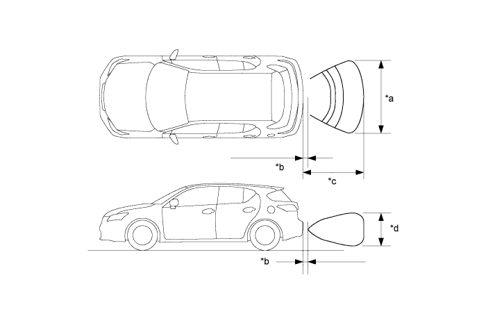
  4. Detection Area

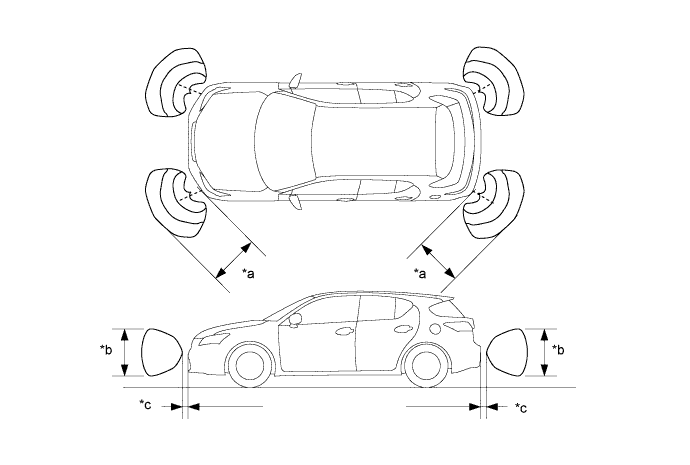
    1. The detection areas of the ultrasonic sensor are as shown in the following illustration.


    2. These detection areas are applicable when positioning a 60 mm (2.36 in.) diameter pole parallel or perpendicular to the ground. The ranges vary depending on the measuring method and type of obstacle.


      Y109229E01


      Text in Illustration (Corner Area:) 
      *a
      Approximately 50 cm (19.7 in.)
      *b
      Approximately 45 cm (17.7 in.)
      *c
      Approximately 20 cm (7.9 in.)
      -
      -

      Y109230E01


      Text in Illustration (Rear Center Area:) 
      *a
      Approximately 170 cm (70.0 in.)
      *b
      Approximately 20 cm (7.9 in.)
      *c
      Approximately 120 cm (47.2 in.)
      *d
      Approximately 60 cm (23.6 in.)