PARKING ASSIST MONITOR SYSTEM > DETAILS


FUNCTION OF MAIN COMPONENTS
*1: Models with HDD Navigation System
*2: Models with DVD Navigation System

Component
Function
Parking Assist ECU
Transmits visual signals, which are composed of a view of the area behind the vehicle taken with the rear television camera assembly and parking assist guide lines, to the multi display.
Navigation Computer Sub-assembly*1
Receives signals from the Remote Touch and outputs a signal to the parking assist ECU.
Display and Navigation Module Display*2
Multi Display
Receives visual signals composed of the area behind the vehicle with parking assist guide lines overlaid from the parking assist ECU, and displays them on the display panel.
Rear Television Camera Assembly
Captures images of the area behind the vehicle and outputs visual signals to the parking assist ECU.
Remote Touch
Switches the assist mode.
Transmission Instrument Panel Shift Assembly
Shift Lever Position Sensor (Select Sensor)
Detects the shift lever position (R, N, D or B), and transmits information about it (lateral movement) to the power management control ECU (HV CPU).
Shift Lever Position Sensor (Shift Sensor)
Detects the shift lever position (R, N, D or B), and transmits information about it (longitudinal movement) to the power management control ECU (HV CPU).
Steering Angle Sensor
Detects the angle of the steering wheel and send the resulting signals to the parking assist ECU.
Power Management Control ECU
Transmits the shift position signal to the parking assist ECU.
Combination Meter Assembly
Transmits the vehicle speed signal to the parking assist ECU.

OPERATING CONDITION
  1. Parking Assist Monitor System

    1. Parking assist monitor system operates when both of the following conditions are met:

      1. The power switch is on (IG).
      2. Reverse (R) is selected.


FUNCTION
  1. Area Displayed on Screen

    1. Rear Television Camera Assembly

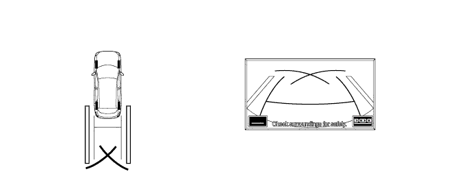
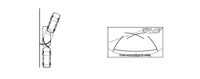
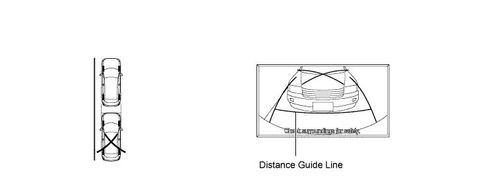
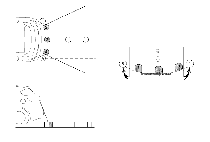
      1. On the display, objects on the right of the vehicle appear on the right side of the display panel, and objects on the left of the vehicle appear on the left side of the display panel.

      2. The rear television camera assembly uses a wide-angle lens. The perceived distance from images that appear on the screen differs from the actual distance.

        Y109290E01

        NOTICE:
        The area displayed on the screen may vary according to vehicle status or road conditions. The area covered by the rear television camera assembly is limited. The rear television camera assembly does not show objects close to either corner of the bumper or under the bumper.

  2. Warning Message

    1. A warning message appears at the bottom, side or center of the screen under the following conditions. The warning message appears in the same language that has been selected by the language selector of the multi display.

      Message Appearing at Bottom or Side of Screen 
      Warning Message
      Condition
      Check surroundings for safety
      During system operation.
      System Initializing
      When the system is restarted after the parking assist ECU detects that a battery terminal has been disconnected and subsequently reconnected.
      Guidance Unavailable
      When an error in the steering angle sensor occurs.

      Message Appearing at Center of Screen 
      Warning Message
      Condition
      System not ready
      When the system is not initialized.

  3. Adjust Function During Part Replacement

    1. The items listed below must always be adjusted whenever one of the following conditions occurs. For details, refer to the Repair Manual.

      Adjustment Items
      Condition
      Neutral steering point in memory
      1. After spiral cable is removed and installed or after connector is disconnected and reconnected, system initializing is displayed.
      2. A wheel alignment is performed.
      3. Suspension parts are removed and reinstalled or replaced.
      Rear television camera assembly optical axis adjustment
      1. Vehicle height has changed due to replacement of suspension parts or tires.
      2. The installation angle of the rear television camera assembly has changed.
      Parking Assist ECU initializing
      Parking assist ECU is replaced.


CONSTRUCTION


  1. Rear Television Camera Assembly


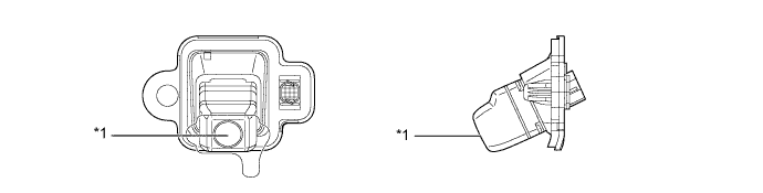
    1. The rear television camera assembly consists of the wide-angle lens and the Charge Coupled Device (CCD).


      Y109218E01


      Text in Illustration 
      *1
      Wide-angle Lens
      -
      -


  2. Multi Display (Parking Assist Monitor Display)


    1. Manual Assist Mode

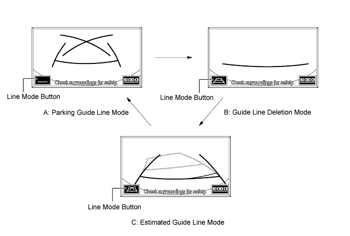
      1. Manual assist mode consists of A: parking guide line mode, B: guide line deletion mode and C: estimated guide line mode. The initial (default) setting for manual assist is estimated guide line mode.
      2. Each mode can be changed by pressing the line mode button.

      3. When manual assist mode is operating, fixed guide lines appear superimposed on a view of the area behind the vehicle. These guide lines can be used to assist the driver while backing the vehicle.


        Y101407E02


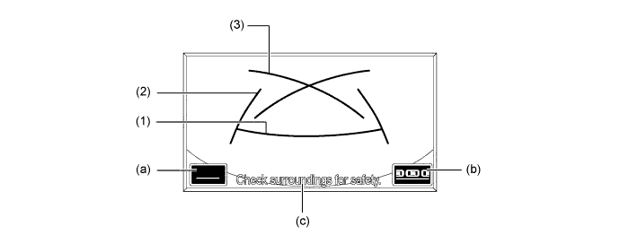
      1. A description of the parking guide line mode display is provided in the following diagram.


        Y101408E02


        Item
        Description
        (1)
        Distance Guide Line (Red)
        Indicates a position on the ground about 0.5 m (1.5 ft.) behind the rear bumper.
        (2)
        Vehicle Width Extension Guide Line
        Indicate the estimated vehicle width extension.
        (3)
        Parking Assist Guide Line
        Indicate the path at which driver should turn the steering wheel fully.
        (a)
        Guide Line Deletion Mode Button
        Pressing this button turns guide line deletion mode on.
        (b)
        Parallel Parking Assist Mode Button
        Pressing this button turns parallel parking assist mode on.
        (c)
        Warning Message Display Area
        Displays a warning message.

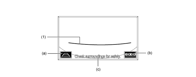
      1. A description of the guide line deletion mode display is provided in the following diagram.


        Y101409E03


        Item
        Description
        (1)
        Distance Guide Line (Red)
        Indicates a position on the ground about 0.5 m (1.5 ft.) behind the rear bumper.
        (a)
        Estimated Guide Line Mode Button
        Pressing this button turns estimated guide line mode on.
        (b)
        Parallel Parking Assist Mode Button
        Pressing this button turns parallel parking assist mode on.
        (c)
        Warning Message Display Area
        Displays a warning message.
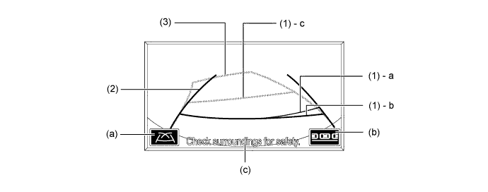
      1. A description of the estimated guide line display is provided in the following diagram.

      Y101410E02


      Item
      Description
      (1) - a
      Distance Guide Line (Green)
      Moves together with estimated guide lines in sync with the steering wheel. The center of the line indicates a position on the ground about 0.5 m (1.5 ft.) behind the rear bumper.
      (1) - b
      Distance Guide Line (Red)
      Indicates a position on the ground about 0.5 m (1.5 ft.) behind the rear bumper.
      (1) - c
      Distance Guide Line (Yellow)
      Moves together with estimated guide lines in sync with the steering wheel. The center of the line indicates a position on the ground about 1.0 m (3.0 ft.) behind the rear bumper.
      (2)
      Vehicle Width Extension Guide Line
      Indicate the estimated vehicle width extension.
      (3)
      Estimated Guide Line
      Moves in sync with the steering wheel to indicate the estimated reverse course of the vehicle.
      (a)
      Parking Guide Line Mode Button
      Pressing this button turns parking guide line mode on.
      (b)
      Parallel Parking Assist Mode Button
      Pressing this button turns parallel parking assist mode on.
      (c)
      Warning Message Display Area
      Displays a warning message.

    2. Parallel Parking Assist Mode

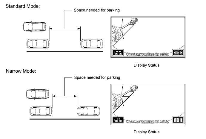
      1. Parallel parking assist is available with the following 2 display modes: standard mode and narrow mode.
      2. Narrow mode is designed for situations in which the parking space is narrower than the standard mode.

      3. Initial (default) parallel parking assist is standard mode.


        Y109455E01

      1. Parallel parking assist will display standard mode and narrow mode using the same design.

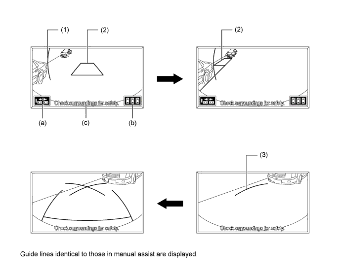
      2. The guide lines displayed for parallel parking assist mode change in accordance with parking maneuvers.


        Y109456E01


        Item
        Description
        (1)
        Green Vertical Line
        Serves as a reference position for starting parallel parking
        (2)
        Green Outline
        1. Serves as a reference position for the intended parking space.
        2. Disappears once the vehicle starts moving backward.
        (3)
        Parking Guide Line
        1. Indicates part of the prospective outer path of the vehicle when the steering is turned fully to the right or left side.
        2. Appears only after guide lines (a) and (b) disappear.
        (a)
        Mode Select Switch
        Changes between standard and narrow modes.
        (b)
        Manual Assist Mode Switch
        Changes between parallel parking assist mode and manual assist mode.
        (c)
        Warning Message Display Area
        Displays a warning message.


OPERATION
  1. Parking Guide Line Mode (Manual Assist) of Parking Assist Monitor System

    1. To use parking guide line mode in manual assist when parking the vehicle in a parking space, perform the following procedure:

      1. Move the shift lever to R.
      2. Select manual assist mode.

      3. An image appears on the display panel as illustrated below.


        Y101415

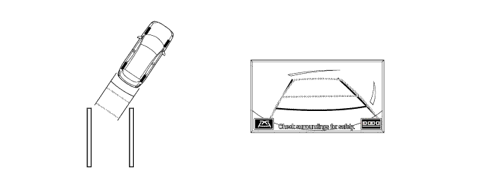
      4. Back the vehicle and stop at the position in which the parking guide line comes in contact with the left side of the intended parking position.

      5. Turn the steering wheel fully to the right and back the vehicle.


        Y101416

      6. Continue backing the vehicle until the vehicle is parallel to the plotted lines.

      7. Once the vehicle is parallel, aim the steering wheel straight ahead and back the vehicle to the target stop position.


        Y101417

  2. Estimated Guide Line Mode (Manual Assist) of Parking Assist Monitor System

    1. To use estimated guide line mode in manual assist when parking the vehicle in a parking space, perform the following procedure:

      1. Move the shift lever to R.
      2. Select manual assist mode.
      3. Select estimated guide line mode.

      4. An image appears on the display panel as illustrated below.


        Y101418


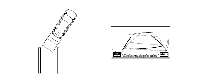
      5. Turn the steering wheel so that the estimated guide lines are within the parking space, and back up carefully.


        Y101419

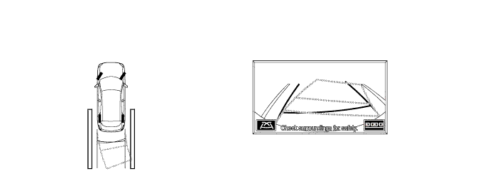
      6. When the rear of the vehicle is within the parking space, turn the steering wheel in order to equalize the left and right intervals between the vehicle width extension lines and the parking space sidelines.

      7. When the vehicle width extension guide lines and the parking space sidelines are parallel, straighten the steering wheel and then carefully back up until the entire vehicle is within the parking space.


        Y101420

  3. Parallel Parking Assist Mode of Parking Assist Monitor System

    1. To use parallel parking assist mode to park the vehicle in the parking space, perform the following procedure:


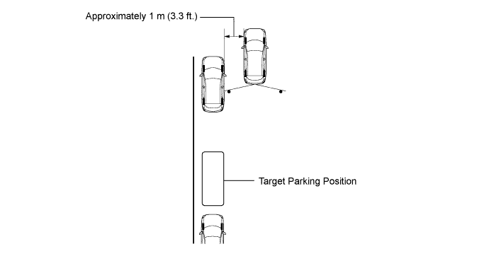
      1. Stop the vehicle parallel to the road or the curb, at a side-to-side clearance of about 1 m (3.3 ft.) from the parked vehicle, approximately one-half car length forward of the parked vehicle.


        Y101421E01

      2. Aim the steering wheel straight ahead and move the shift lever to R.
      3. Parallel parking assist mode is automatically selected.

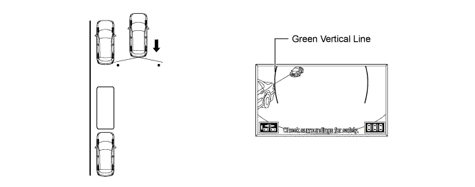
      4. An image shows on the display panel as illustrated below.


        Y101422


      5. Drive the vehicle straight back and stop when the green vertical line of the target parking position is aligned with the rear end of the parked vehicle.


        Y109457E01


      6. When the steering wheel is turned, the green outline will appear. At this time, the green vertical line opposite to the target parking position will disappear when the steering wheel is turned more than 90 degrees.


        Y109458E01


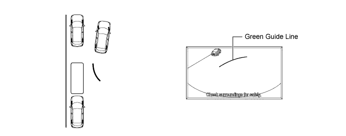
      7. Continue turning the steering wheel, and the green outline will move in the direction of the target parking position, while the outline changes into a shape as illustrated below. Keep turning the steering wheel until the green outline reaches the target parking position.


        Y109459E01


      8. However, if the steering wheel is turned too much, the message as shown in the illustration below is displayed and the green outline will change to red to inform the driver that the assist operation is not possible. Also, when your vehicle is too far away from the shoulder, the same condition will occur even when adjusting the green outline to a normal position.


        Y101426E02


      9. Keep the steering wheel in the same position and start backing up. The green vertical line and green outline will disappear, and a parking guide line appears in the direction of the target parking position.


        Y101427E02


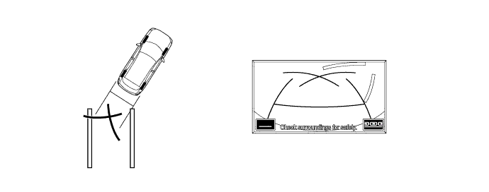
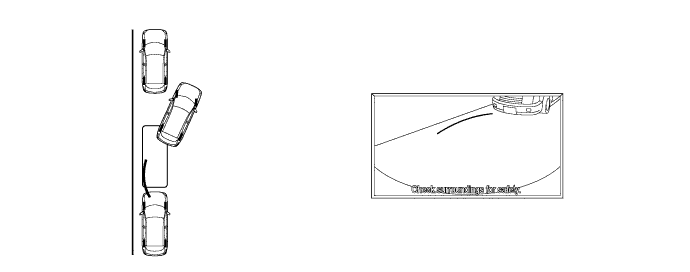
      10. Keep the steering wheel in the same position and back up. Stop when the parking guide line reaches the left end of the target parking position.


        Y101428

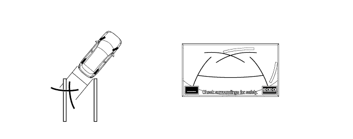
      11. With the vehicle at a standstill, fully turn the steering wheel in the opposite direction. Then, as shown in the illustration below, the same guide line appears as in manual assist mode.

      12. The same screen displays as those in manual assist mode will appear in the following steps, guide line mode (parking guide line, guide line deletion, estimated guide line) is the mode set for manual assist.


        Y101429


      13. Using the distance guide line slowly back the vehicle until the vehicle is parallel to the road or curb, while paying attention to the vehicles in front and in back. The parking maneuver is completed once the vehicle is parallel.


        Y101430E02


FAIL-SAFE
  1. The table below indicates the malfunction detection conditions of the components in this system.

    Malfunction Parts
    Detection Item
    Function
    Steering Angle Sensor
    1. Transmission of sensor malfunction signal
    2. Open circuit in sensor signal
    3. Communication malfunction between the steering angle sensor and parking assist ECU
    Displays "Guidance Unavailable"
    Transmission of signal to indicate that neutral steering point correction is incomplete
    Displays "System Initializing"
    Rear Television Camera Assembly
    Transmission of camera malfunction signal
    Stop signal reception and displays a dark screen
    Parking Assist ECU
    Malfunction of parking assist ECU
    Stops system operation


DIAGNOSIS
  1. The parking assist monitor system is equipped with a diagnosis function which can display the diagnosis menus. The method for entering the diagnosis menu screen is the same as the method used for the multi display. For details, refer to the Repair Manual.