MONITOR SYSTEM > DETAILS


FUNCTION OF MAIN COMPONENTS

Component
Function
Rear Television Camera Assembly
Transmits a video signal of the area behind the vehicle to the display and navigation module display.
Inner Rear View Mirror Assembly
  1. Receives signals from the back-up light relay and turns the rear television camera assembly on and off.
  2. Displays the image transmitted by the rear television camera assembly on the screen.
Shift Lever Assembly
Select Sensor
Detects the shift state (R, N, D or B), and transmits information about it (lateral movement) to the power management control ECU (HV CPU).
Shift Sensor
Detects the shift state (R, N, D or B), and transmits information about it (longitudinal movement) to the power management control ECU (HV CPU).
Power Management Control ECU
Judges the shift lever position (R, N, D or B) based on the signals from the transmission instrument panel shift assembly. Turns on the back-up light relay when reversing.
Back-up Light Relay
Sends a reverse signal to the inner rear view mirror assembly or navigation receiver assembly.

OPERATING CONDITION
  1. This system operates when both the following conditions have been met:

    1. The power switch is on (READY).

    2. Reverse (R) is selected.


FUNCTION


  1. Area Displayed on Screen

    1. On the display, objects on the right of the vehicle appear on the right side of the display panel, and objects on the left of the vehicle appear on the left side of the display panel.


    2. The rear television camera assembly uses a wide-angle lens. The perceived distance from images that appear on the screen will differ from the actual distance.
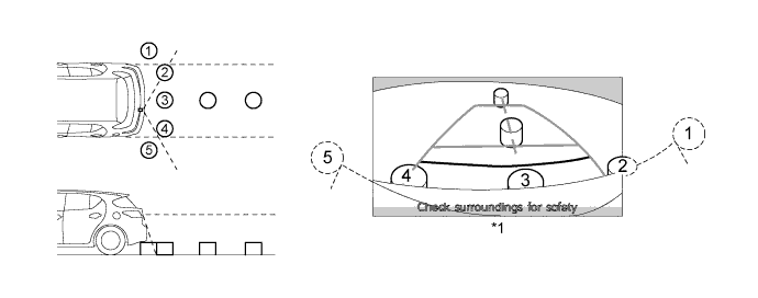

      Y109291E01


      Text in Illustration 
      *1
      Display Status
      -
      -

      HINT:
      1. The area displayed on screen may vary according to vehicle status or road conditions.
      1. The area covered by the rear television camera assembly is limited. The rear television camera assembly does not show objects close to either corner of the bumper or show the area under the bumper.
CONSTRUCTION


  1. Inner Rear View Mirror Assembly

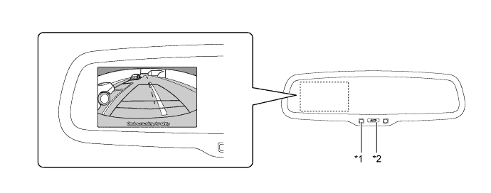
    1. A 3.3 inch display is built in the inner rear view mirror assembly.

    2. When reverse is selected, the display shows the image from the rear television camera assembly. The AUTO switch is used to turn the display on or off.


    3. When the video is being displayed on the inner rear view mirror assembly, the guide lines for park assist are also displayed.

      AUTO (Display On/Off) Switch
      LED
      Display
      On
      Green
      Available
      Off
      Amber
      Not Available


      Y109226E01


      Text in Illustration 
      *1
      LED
      *2
      AUTO (Display On/Off) Switch


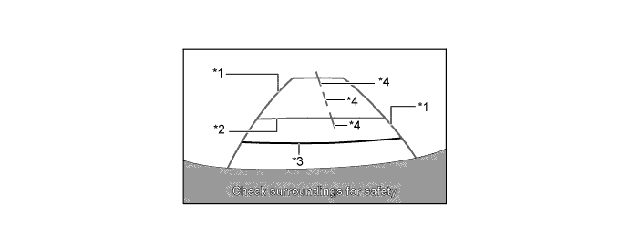
    4. A description of the parking guide line mode display is provided in the following diagram.


      Y109427E01


      Text in Illustration 
      *1
      Vehicle Width Extension Guide Lines (Blue)
      *2
      Distance Guide Line (Blue)
      *3
      Distance Guide Line (Red)
      *4
      Vehicle Center Guide Lines (Blue)

      Item
      Description
      Vehicle Width Extension Guide Lines (Blue)
      Indicate the estimated vehicle width extension.
      Distance Guide Line (Blue)
      Indicates a position on the ground about 1 m (3 ft.) behind the rear bumper.
      Distance Guide Line (Red)
      Indicates a position on the ground about 0.5 m (1.5ft.) behind the rear bumper.
      Vehicle Center Guide Lines (Blue)
      These lines indicate the estimated position on the ground of the center of the vehicle.


FAIL-SAFE
  1. The table below indicates fail-safe operation when a malfunction is detected:

    Malfunctioning Part
    Detection Item
    Function
    Rear Television Camera Assembly
    Rear television camera assembly malfunction signal is detected.
    If a signal from the rear television camera assembly is not received for approximately 1 second, the screen changes to blue for approximately 3 seconds and then turns off.