LIGHTING SYSTEM > DETAILS |
| FUNCTION OF MAIN COMPONENTS |
Daytime Running Light System
| Component | Function | |
| Main Body ECU (Multiplex Network Body ECU) | The main body ECU (multiplex network body ECU) receives various signals and illuminates the daytime running lights via the DRL relay. | |
| DRL Relay | The DRL relay supplies power to the daytime running lights. | |
| Headlight Dimmer Switch Assembly | Light Control Switch | The light control switch outputs a light control signal and transmits it to the main body ECU (multiplex network body ECU). |
| Power Management Control ECU | The power management control ECU receives the power switch push signal, outputs a READY signal and transmits it to the main body ECU (multiplex network body ECU). | |
| Combination Meter Assembly | Multi-information Display | The multi-information display changes to customize mode to display the daytime running light on/off condition when the steering pad switch assembly is operated. |
| Steering Pad Switch Assembly | DISP Switch |
|
| Navigation Computer Sub-assembly*1 | The navigation computer sub-assembly receives the Remote Touch signal, transmits it to the main body ECU (multiplex network body ECU) and transmits the display changing signal to the center instrument cluster finish panel assembly (multi display). | |
| Display and Navigation Module Display*2 | The display and navigation module display receives the Remote Touch signal, transmits it to the main body ECU (multiplex network body ECU) and transmits the display changing signal to the center instrument cluster finish panel assembly (multi display). | |
| Center Instrument Cluster Finish Panel Assembly (Multi Display)*3 | The multi display changes to customize mode to display the daytime running light on/off condition when the Remote Touch is operated. | |
| Remote Touch*3 |
| |
Light Emitting Diode (LED) Headlight System
| Component | Function | |
| Main Body ECU (Multiplex Network Body ECU) | The main body ECU (multiplex network body ECU) receives the HEAD position signal from the light control switch and transmits a signal to the HEAD relay. | |
| Headlight Dimmer Switch Assembly | Light Control Switch | The light control switch transmits a HEAD position signal to the main body ECU (multiplex network body ECU). |
| HEAD Relay | The HEAD relay supplies power to the LED driver modules. | |
| Headlight Assembly | Light Emitting Diode (LED) | The Light Emitting Diode (LED) light shines ahead over a broader area and further forward, increasing the area visible to the driver. |
| LED Driver Module | The LED driver module keeps a constant level of direct current applied to the LED, achieving stable LED illumination. | |
| Combination Meter Assembly | Taillight Indicator Light | The taillight indicator lights up to inform the driver when the taillights turn on. |
| Master Warning Light | The master warning light illuminates to inform the driver when the LED driver module detects malfunctions in this system. | |
| Multi-information Display | The multi-information display displays a warning message to inform the driver when the LED driver module detects a malfunction in this system. | |
Automatic Headlight Beam Level Control System (Models with LED Headlight System)
| Component | Function | |
| Headlight Leveling ECU Assembly |
| |
| Headlight Assembly LH/RH | Headlight Leveling Motor LH/RH |
|
| Main Body ECU (Multiplex Network Body ECU) | The main body ECU (multiplex network body ECU) receives a HEAD position signal from the light control switch and transmits it to the headlight leveling ECU assembly. | |
| Headlight Dimmer Switch Assembly | Light Control Switch | The light control switch transmits a HEAD position signal to the main body ECU (multiplex network body ECU). |
| Rear Height Control Sensor Assembly LH | The rear height control sensor assembly LH detects vehicle movement and transmits a signal to the headlight leveling ECU assembly. | |
| Combination Meter Assembly | The combination meter assembly transmits a vehicle speed signal to the headlight leveling ECU assembly. | |
| Combination Meter Assembly | Automatic Headlight Beam Level Indicator Light | The automatic headlight beam level indicator light flashes to inform the driver when the headlight leveling ECU assembly detects malfunctions in this system. |
Manual Headlight Beam Level Control System
| Component | Function | |
| Headlight Leveling Switch | Sends control signals to the headlight leveling motor. | |
| Headlight Assembly LH/RH | Headlight Leveling Motor LH/RH |
|
Automatic Light Control System
| Component | Function | |
| Main Body ECU (Multiplex Network Body ECU) | The main body ECU (multiplex network body ECU) receives various signals and illuminates the headlights, taillights, position lights and license plate lights. | |
| Dimmer Relay | The dimmer relay supplies power to the high beams. | |
| HEAD Relay | The HEAD relay supplies power to the low beams. | |
| TAIL Relay | The TAIL relay supplies power to the taillights, position lights and license plate lights. | |
| Power Management Control ECU | The power management control ECU receives the power switch push signal, outputs a READY signal and transmits it to the main body ECU (multiplex network body ECU). | |
| Automatic Light Control Sensor | The automatic light control sensor detects the ambient light level. | |
| Headlight Dimmer Switch Assembly | Light Control Switch | The light control switch transmits an AUTO position signal to the main body ECU (multiplex network body ECU). |
| Combination Meter Assembly | Taillight Indicator Light | The taillight indicator lights up to inform the driver when the taillights turn on. |
| Multi-information Display | The multi-information display can be changed to customize mode to display the sensitivity of the light control sensor when the steering pad switch assembly is operated. | |
| Steering Pad Switch Assembly | DISP Switch |
|
| Navigation Computer Sub-assembly*1 | The navigation computer sub-assembly receives the Remote Touch signal, transmits it to the main body ECU (multiplex network body ECU) and transmits the display changing signal to the center instrument cluster finish panel assembly (multi display). | |
| Display and Navigation Module Display*2 | The display and navigation module display receives the Remote Touch signal, transmits it to the main body ECU (multiplex network body ECU) and transmits the display changing signal to the center instrument cluster finish panel assembly (multi display). | |
| Center Instrument Cluster Finish Panel Assembly (Multi Display)*3 | The multi display changes to customize mode to display the automatic light control system setting condition when the Remote Touch is operated. | |
| Remote Touch*3 |
| |
Light Auto Turn-off System
| Component | Function | |
| Main Body ECU (Multiplex Network Body ECU) | The main body ECU (multiplex network body ECU) receives various signals, and turns off the exterior lights. | |
| Power Management Control ECU | The power management control ECU receives the power switch push signal, outputs a READY signal and transmits it to the main body ECU (multiplex network body ECU). | |
| Dimmer Relay | The dimmer relay shuts down the power to the high beams. | |
| HEAD Relay | The HEAD relay shuts down the power to the low beams. | |
| TAIL Relay | The TAIL relay shuts down the power to the taillights, position lights and license plate lights. | |
| FR FOG Relay*1 | The FR FOG relay shuts down the power to the front fog lights. | |
| RR FOG Relay*2 | The RR FOG relay shuts down the power to the rear fog light. | |
| Headlight Dimmer Switch Assembly | Light Control Switch | The light control switch transmits a light control position signal to the main body ECU (multiplex network body ECU). |
| Courtesy Switch | Front LH/RH, Rear LH/RH, Back Door | The courtesy switch detects whether a door is open or closed and transmits a signal to the main body ECU (multiplex network body ECU). |
| Door Unlock Detection Switch | Front LH/RH, Rear LH/RH | The door unlock detection switch detects whether a door is locked or unlocked and transmits a signal to the main body ECU (multiplex network body ECU). |
| Door Control Receiver | The door control receiver receives the ID code from the door control transmitter in the actuation area and transmits it to the main body ECU (multiplex network body ECU) via the certification ECU (smart key ECU assembly). | |
| Certification ECU (Smart Key ECU Assembly) | The certification ECU (smart key ECU assembly) judges and certifies the ID code from the door control receiver. | |
| Combination Meter Assembly | Multi-information Display | The multi-information display can be changed to customize mode to display the operation time of the light turn-off when the steering pad switch assembly is operated. |
| Steering Pad Switch Assembly | DISP Switch |
|
| Navigation Computer Sub-assembly*3 | The navigation computer sub-assembly receives the Remote Touch signal, transmits it to the main body ECU (multiplex network body ECU) and transmits the display changing signal to the center instrument cluster finish panel assembly (multi display). | |
| Display and Navigation Module Display*4 | The display and navigation module display receives the Remote Touch signal, transmits it to the main body ECU (multiplex network body ECU) and transmits the display changing signal to the center instrument cluster finish panel assembly (multi display). | |
| Center Instrument Cluster Finish Panel Assembly (Multi Display)*5 | The multi display changes to customize mode to display the light turn-off system setting condition when the Remote Touch is operated. | |
| Remote Touch*5 |
| |
Door Mirror Foot Light System
| Component | Function | |
| Main Body ECU (Multiplex Network Body ECU) | The main body ECU (multiplex network body ECU) receives various signals and illuminates the door mirror foot lights. | |
| Door Lock Switch | Driver, Front Passenger | The door lock switch outputs the lock/unlock signal to the main body ECU (multiplex network body ECU) or multiplex network master switch assembly. |
| Certification ECU (Smart Key ECU Assembly) | The certification ECU (smart key ECU assembly) judges and certifies the ID code. | |
| Power Management Control ECU | The power management control ECU receives the shift lever position signals from the shift lever position sensor (select sensor, shift sensor) and transmits them to the main body ECU (multiplex network body ECU). | |
| Courtesy Switch | Front LH/RH, Rear LH/RH, Back Door | The courtesy switch detects whether a door is open or closed and transmits a signal to the main body ECU (multiplex network body ECU). |
| Door Unlock Detection Switch | Front LH/RH, Rear LH/RH | The door unlock detection switch detects whether a door is locked or unlocked and transmits a signal to the main body ECU (multiplex network body ECU). |
| Multiplex Network Master Switch Assembly | The multiplex network master switch assembly sends the driver side door lock switch signal to the main body ECU (multiplex network body ECU). | |
| Combination Meter Assembly | Multi-information Display | The multi-information display can be changed to customize mode to display the operation time of the door mirror foot light when the steering pad switch assembly is operated. |
| Steering Pad Switch Assembly | DISP Switch |
|
| Navigation Computer Sub-assembly*1 | The navigation computer sub-assembly receives the Remote Touch signal, transmits it to the main body ECU (multiplex network body ECU) and transmits the display changing signal to the center instrument cluster finish panel assembly (multi display). | |
| Display and Navigation Module Display*2 | The display and navigation module display receives the Remote Touch signal, transmits it to the main body ECU (multiplex network body ECU) and transmits the display changing signal to the center instrument cluster finish panel assembly (multi display). | |
| Center Instrument Cluster Finish Panel Assembly (Multi Display)*3 | The multi display changes to customize mode to display the door mirror foot light system setting condition when the Remote Touch is operated. | |
| Remote Touch*3 |
| |
| OPERATING CONDITION |
Daytime Running Light System
The daytime running lights illuminate when the following conditions are met:
Light Auto Turn-off System
The light auto turn-off system operates as follows:
| Function | Operation Condition |
| Driver Door-linked | When all of the following conditions are met, the exterior lights automatically turn off:
|
| Driver Door-linked*1 | When all of the following conditions are met, the exterior lights automatically turn off:
|
| Driver Door-linked*2 | When all of the following conditions are met, the exterior lights automatically turn off:
|
When all of the following conditions are met, the low beam automatically turn off:
|
Door Mirror Foot Light System
The door mirror foot light system operates as follows:
| Function | Operation Condition |
| Actuation Area-linked | When all of the following conditions are met, the door mirror lights automatically turn on:
|
When the following condition is met, the door mirror lights automatically turn off:
| |
| Door Unlock-linked | When all of the following conditions are met, the door mirror lights automatically turn on:
|
| Door Lock-linked | When one of the following conditions is met, the door mirror lights automatically turn off:
|
| Door-linked | When the following condition is met, the door mirror lights automatically turn on:
|
| Delay | When approximately 15 seconds elapse after one of the following conditions is met, the door mirror lights turn off:
|
| Shift Position-linked | When both of the following conditions are met, the door mirror lights automatically turn off:
|
| FUNCTION |
Automatic Headlight Beam Level Control System (Models with LED Headlight System)
The automatic headlight beam level control system mainly consists of the headlight leveling ECU assembly, rear height control sensor assembly and 2 headlight leveling motors. The headlight leveling ECU assembly controls the system.
The ECU detects the movement of the suspension from the rear height control sensor assembly LH and the vehicle speed from the combination meter assembly.
The ECU then controls the headlight leveling motor based on this information, in order to change the headlight reflector angle.
When the headlight leveling ECU assembly detects that the vehicle is stopped and the power switch is on (READY), the ECU executes the initial setting of the stepper motors.
| CONSTRUCTION |
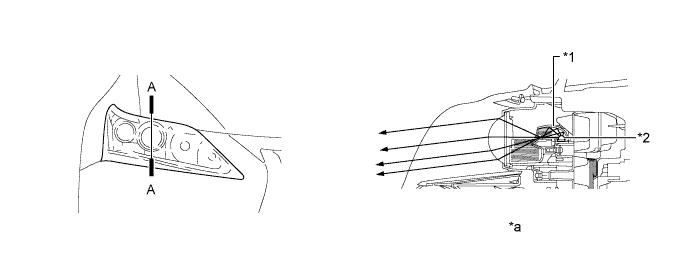
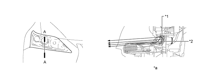
LED Headlight System
Projector Type LED Light

| *1 | Reflector | *2 | LED |
| *a | A-A Cross Section | - | - |
Parabolic Type LED Light

| *1 | LED | *2 | Reflector |
| *a | A-A Cross Section | - | - |
LED Driver Module
| FAIL-SAFE |
LED Headlight System
The LED driver module executes the fail-safe actions listed below in accordance with the problem that has been detected.
| Problem | Outline |
| Abnormal Input Voltage | If the voltage that is input to LED driver module deviates from the normal operating voltage (10 to 16 V), the LED driver module stops illuminating the headlights. It resumes illuminating the headlights once the voltage reverts to the operating voltage range. |
| Abnormal Output (Open Circuit or Short Circuit) | If an abnormal condition (open or short) occurs in the voltage that is output by the LED driver module, the LED driver module stops illuminating the headlights and will maintain this state until the power is reinstated. Power is reinstated by turning the headlight dimmer switch assembly (light control switch) from off to on. |
Automatic Headlight Beam Level Control System (Models with LED Headlight System)
If the headlight leveling ECU assembly detects a malfunction in the automatic headlight beam level control system, it will take the actions indicated in the table below.
| Trouble Area | System Operation | Automatic Headlight Level Indicator Light | Master Warning Light |
| Headlight Leveling ECU Assembly | Stops at current condition. | - | - |
| Vehicle Speed Signal | Continues control only when the vehicle is stopped. | Flashes | Illuminates |
| Rear Height Control Sensor Assembly Signal |
| Flashes | Illuminates |
| Headlight Leveling Motor |
| Flashes | Illuminates |
| DIAGNOSIS |
LED Headlight System
When the main body ECU (multiplex network body ECU) detects malfunctions in the LED headlight system, Diagnostic Trouble Codes (DTCs) are stored in memory.
The DTCs can be read using the intelligent tester. For details, refer to the Repair Manual.
Automatic Headlight Beam Level Control System (Models with LED Headlight System)
When the headlight leveling ECU assembly detects malfunctions in the automatic headlight beam level control system, Diagnostic Trouble Codes (DTCs) are stored in memory.
The DTCs can be read using the intelligent tester. For details, refer to the Repair Manual.
Automatic Light Control System
When the main body ECU (multiplex network body ECU) detects malfunctions in the automatic light control system, Diagnostic Trouble Codes (DTCs) are stored in memory.
The DTCs can be read using the intelligent tester. For details, refer to the Repair Manual.