Home Brake BRAKE CONTROL / DYNAMIC CONTROL SYSTEMS ELECTRONICALLY CONTROLLED BRAKE SYSTEM

DTC    C1247/47    Stroke Sensor Malfunction

DTC    C1346/71    Stroke Sensor Zero Point Learning Malfunction (Test Mode DTC)

DTC    C1392/48    Stroke Sensor Zero Point Calibration Undone

for Preparation Click here


DESCRIPTION

The stroke sensor inputs the pedal stroke into the skid control ECU.
DTC C1346/71 will be cleared when the brake pedal stroke sensor sends a stroke sensor signal or when Test Mode ends. DTC C1346/71 is output only in Test Mode.

DTC Code
INF Code
DTC Detection Condition
Trouble Area
C1247/47
211
Sensor supply voltage (VCM1) is 4.75 V or less, or 5.25 V or more for 0.2 seconds or more.
  1. Open or short in brake pedal stroke sensor power supply circuit
  2. Improperly connected connector, deformation or corrosion of terminals
  3. Brake booster with master cylinder (Skid control ECU)

212
Sensor output voltage 1 (SKS1) is less than 5.5%, or 94% or more (less than 0.15 V, or 4.85 V or more) of sensor supply voltage (VCM1) for 0.2 seconds or more.
  1. Open or short in wire harness
  2. Improperly connected connector, deformation or corrosion of terminals
  3. Brake pedal stroke sensor

213
Sensor output voltage 2 (SKS2) is less than 5.5%, or 94% or more (less than 0.15 V, or 4.85 V or more) of sensor supply voltage (VCSK) for 0.2 seconds or more.


214
Either of the following is detected:
  1. Fluctuation of sensor output 1 (SKS1) is out of specification.
  2. The difference between the present value and last value of sensor output voltage 1 (SKS1) is 8.5% or more (0.43 V or more) of sensor supply voltage (VCM1) for 0.2 seconds or more.


215
Either of the following is detected:
  1. Fluctuation of sensor output 2 (SKS2) is out of specification.
  2. The difference between the present value and last value of the sensor output voltage 2 (SKS2) is 8.5% or more (0.43 V or more) of the sensor supply voltage (VCM1) for 0.2 seconds or more.


218
An excessive difference between the change in sensor output 1 (SKS1) and sensor output 2 (SKS2) is detected for 0.2 seconds or more.


219
Sensor data is invalid for 0.2 seconds or more.
(Skid control ECU internal monitor circuit malfunction.)


223
Sensor data is invalid for 0.2 seconds or more.
(Open, short, or noise.)

C1392/48
-
Zero point calibration of stroke sensor is unfinished.
  1. Brake pedal stroke sensor zero point calibration incomplete (Initialization and calibration of linear solenoid valve incomplete)
  2. Brake booster with master cylinder (Skid control ECU)
C1346/71
-
Detected only during Test Mode.
  1. Brake pedal stroke sensor
  2. Brake pedal stroke sensor circuit

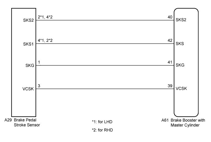
WIRING DIAGRAM


C235540E02


INSPECTION PROCEDURE

NOTICE:
When replacing the brake booster with master cylinder (skid control ECU) or brake pedal stroke sensor, perform initialization and calibration of the linear solenoid valve (Click here).

HINT:
Check the condition of each related circuit connector before troubleshooting (Click here).

1.CHECK BRAKE PEDAL
  1. Check that the brake pedal and the brake pedal stroke sensor are properly installed and that the pedal can be depressed normally.

  1. Check and adjust the brake pedal height

    C
    REPLACE BRAKE BOOSTER WITH MASTER CYLINDER (Click here)

    D
    REPLACE BRAKE BOOSTER WITH MASTER CYLINDER (Click here)
    A

    REPLACE BRAKE PEDAL STROKE SENSOR (Click here)