 |
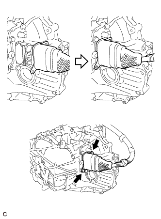
Place the motor cable connector shell in position and install it with the 2 bolts.
- Torque:
- 10 N*m{ 102 kgf*cm , 7 ft.*lbf }
MOTOR CABLE > INSTALLATION |
| 1. INSTALL MOTOR CABLE |
Install the motor cable to the hybrid transaxle assembly with the 3 bolts.
Engage the 2 claws to install a new terminal cap.
|
Place the motor cable connector shell in position and install it with the 2 bolts.
Connect the 3 clamps.
| 2. INSTALL INVERTER TRAY BRACKET |
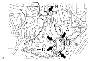 |
Position the inverter tray bracket as shown in the illustration.
Temporarily install bolt B to the inverter tray bracket.
Tighten the 5 bolts to the inverter tray bracket in the order bolt A, bolt C, bolt D, bolt E and bolt B.
Connect the 2 clamps to the inverter tray bracket.
| 3. INSTALL INVERTER RESERVE TANK ASSEMBLY |
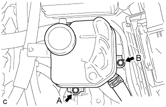 |
Temporarily install bolt A to the inverter reserve tank assembly.
Tighten the 2 bolts to the inverter reserve tank assembly in the order bolt B and bolt A.
| 4. INSTALL INVERTER WITH CONVERTER ASSEMBLY |
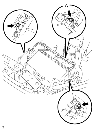 |
Temporarily install the inverter with converter assembly with the 3 bolts.
Tighten bolt A.
Tighten the 2 bolts.
| 5. CONNECT WATER HOSE |
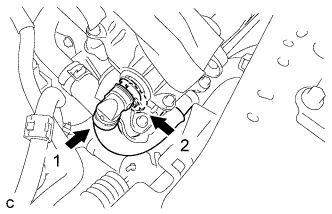 |
Connect the water hose to the inverter with converter assembly and lock the hose with the retainer.
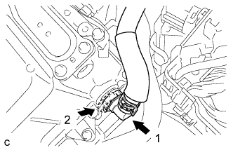 |
Connect the water hose to the inverter with converter assembly and lock the hose with the retainer.
| 6. CONNECT NO. 2 ENGINE ROOM WIRE |
Disconnect the No. 2 engine room wire from the protector.
Connect the No. 2 engine room wire with the bolt and 2 claws.
Install the No. 1 relay block cover and 2 clamps.
Install the relay block cover.
| 7. REMOVE INVERTER COVER |
Remove the 9 bolts and inverter cover.
| 8. CONNECT NO. 2 ENGINE WIRE |
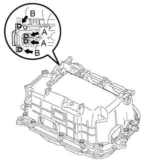 |
Temporarily install the No. 2 engine wire (high voltage cables of the air conditioning) and 4 bolts to the inverter assembly by hand.
Fully tighten the 4 bolts.
Connect the harness clamp.
| 9. CONNECT MOTOR CABLE |
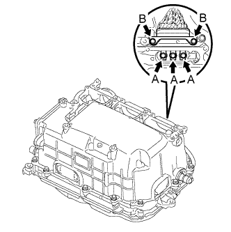 |
Temporarily install the high voltage cable of the motor (MG2) and 5 bolts to the inverter assembly by hand.
Fully tighten the 5 bolts.
Connect the harness clamp.
| 10. CONNECT GENERATOR CABLE |
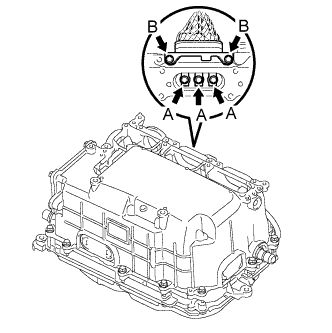 |
Temporarily install the high voltage cable of the generator cable (MG1) and 5 bolts to the inverter assembly by hand.
Fully tighten the 5 bolts.
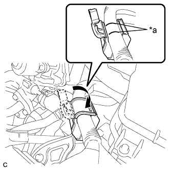 |
Install the generator cable and cover.
| *a | Align Mark |
| 11. CONNECT FRAME WIRE |
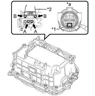 |
Temporarily install the frame wire (high voltage cables of the hybrid battery) and 4 bolts to the inverter assembly by hand.
| *1 | Interlock |
| *2 | High voltage cables of the hybrid battery |
| *a | Front view of frame wire connector |
Fully tighten the 4 bolts.
Connect the 2 harness clamps.
| 12. CHECK HIGH VOLTAGE CABLE CONNECTION |
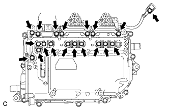 |
Check that each connector and terminal is firmly installed.
| 13. INSTALL INVERTER COVER |
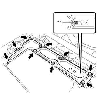 |
Install the inverter cover with the 9 bolts to the inverter with converter assembly.
| *1 | Interlock |
| 14. INSTALL ENGINE ROOM MAIN WIRE |
Install the bolt, clamp and clip, and connect the engine room main wire.
Install the bolt.
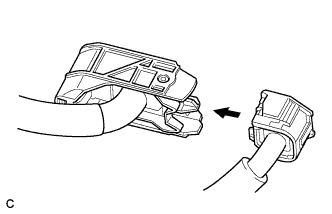 |
Connect the engine wire to the engine room main wire.
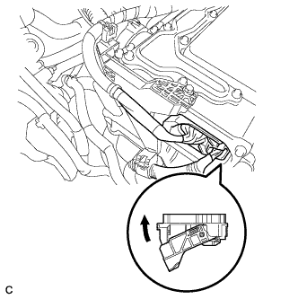 |
Connect the connector to the inverter with converter assembly and lock the connector with the lock lever.
| 15. INSTALL NO. 1 INVERTER BRACKET |
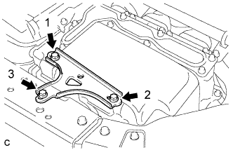 |
Temporarily install the No. 1 inverter bracket with the 3 bolts.
Tighten the 3 bolts in the order shown in the illustration.
| 16. INSTALL SERVICE PLUG GRIP |
Wear insulated gloves and install the service plug grip in the order shown in the illustration.
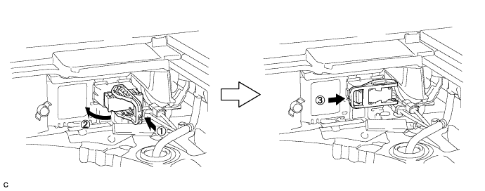
Rotate the handle of the service plug grip 90° toward the battery and slide it in the direction shown by the arrow until a click sound is heard.
| 17. CONNECT CABLE TO NEGATIVE AUXILIARY BATTERY TERMINAL |
| 18. INSTALL REAR FLOOR BOARD UPPER NO. 3 PLATE |
Engage the 4 claws and 2 guides to install the rear floor board upper No. 3 plate.
| 19. INSTALL DECK FLOOR BOX RH |
Engage the 6 guides.
Install the deck floor box RH with the clip.
| 20. INSTALL REAR NO. 3 FLOOR BOARD |
Install the rear No. 3 floor board.
| 21. INSTALL REAR DECK FLOOR BOX |
Install the rear deck floor box.
| 22. INSTALL REAR NO. 2 FLOOR BOARD |
Install the rear No. 2 floor board.
| 23. ADD COOLANT (for Inverter) |
| DTC No. | Detection Item |
| P0A01-726 | Motor Electronics Coolant Temperature Sensor Circuit Range / Performance |
| P0A04-725 | Motor Electronics Coolant Temperature Sensor Circuit Intermittent |
| P0A08-264 | DC / DC Converter Status Circuit |
| P0A78-284 | Drive Motor "A" Inverter Performance |
| P0A78-286 | Drive Motor "A" Inverter Performance |
| P0A7A-322 | Generator Inverter Performance |
| P0A7A-324 | Generator Inverter Performance |
| P0A93-346 | Inverter Cooling System Performance |
| P0A94-553 | DC / DC Converter Performance |
| P0A94-557 | DC / DC Converter Performance |
| P0AEE-277 | Motor Inverter Temperature Sensor "A" Circuit Range / Performance |
| P0AF1-276 | Drive Motor Inverter Temperature Sensor "A" Circuit Intermittent / Erratic |
| P0BCD-315 | Generator Inverter Temperature Sensor Circuit Range / Performance |
| P0BD0-314 | Generator Inverter Temperature Sensor Circuit Intermittent / Erratic |
| P0C39-626 | DC / DC Converter Temperature Sensor "A" Range / Performance |
| P0C3C-625 | DC / DC Converter Temperature Sensor "A" Intermittent / Erratic |
| P0C3E-628 | DC / DC Converter Temperature Sensor "B" Range / Performance |
| P0C41-627 | DC / DC Converter Temperature Sensor "B" Intermittent / Erratic |
| P0C73-776 | Motor Electronics Coolant Pump "A" Control Performance |
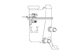 |
Slowly pour coolant into the reserve tank until it reaches the full line.
When using the intelligent tester:
Connect the intelligent tester to the DLC3.
Turn the power switch on (IG).
Enter the following menus: Powertrain / Hybrid Control / Active Test / Activate the Water Pump.
Keep the coolant at the full line in the reserve tank to compensate for the drop in coolant level when the air bleeds.
When not using the intelligent tester:
Turn the power switch on (READY). [*1]
Turn the power switch off and add coolant to the full line because the coolant level drops as the air bleeds. [*2]
Repeat steps [*1] and [*2] until air bleeding from the cooling system is completed.
After the air is completely bled from the cooling system, tighten the reserve tank cap.
|
Add coolant to the full line of the reserve tank.
| 24. INSPECT FOR COOLANT LEAK (for Inverter) |
Remove the reserve tank cap.
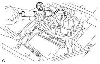 |
Install a radiator cap tester.
Pump the radiator cap tester to 122 kPa (1.2 kgf/ cm2, 18 psi), and then check that the pressure does not drop.
Reinstall the reserve tank cap.
| 25. INSTALL RADIATOR SUPPORT OPENING COVER |
Install the radiator support opening cover with the 9 clips.
| 26. INSTALL INVERTER COVER ASSEMBLY LH (w/ Cover) |
Engage the claw and install the inverter cover assembly LH.
Install the 2 clips.
| 27. INSTALL NO. 1 ENGINE UNDER COVER |
| 28. INSTALL FRONT LOWER BUMPER ABSORBER |