Home Power Source / Network POWER DISTRIBUTION INTEGRATION RELAY

INTEGRATION RELAY > ON-VEHICLE INSPECTION

for Preparation Click here


1. INSPECT NO. 1 INTEGRATION RELAY

HINT:
  1. This inspection is not for the No. 1 integration relay itself, but for the wire harness that is connected to the No. 1 integration relay. If the result is within the specified condition, the No. 1 integration relay may be malfunctioning.
  2. After the wire harness has been repaired, disconnect all connectors that are connected to the No. 1 integration relay, and turn the power switch on (READY) to clear the DTCs.


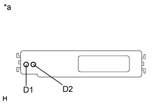
  1. Diagnosis Terminal


      E184982E05
    1. Measure the voltage according to the value(s) in the table below.

      Standard Voltage :
      Tester Connection
      Condition
      Specified Condition
      D1 - Body ground
      Power switch on (IG) or (READY)
      3.5 to 5.0 V
      D2 - Body ground
      Power switch on (IG) or (READY)
      3.5 to 5.0 V

      HINT:
      If the result is not as specified, one of the electrical load connected to the No. 1 integration relay may be malfunctioning.

      Text in Illustration 
      *a
      Component with harness connected
      (No. 1 Integration Relay)