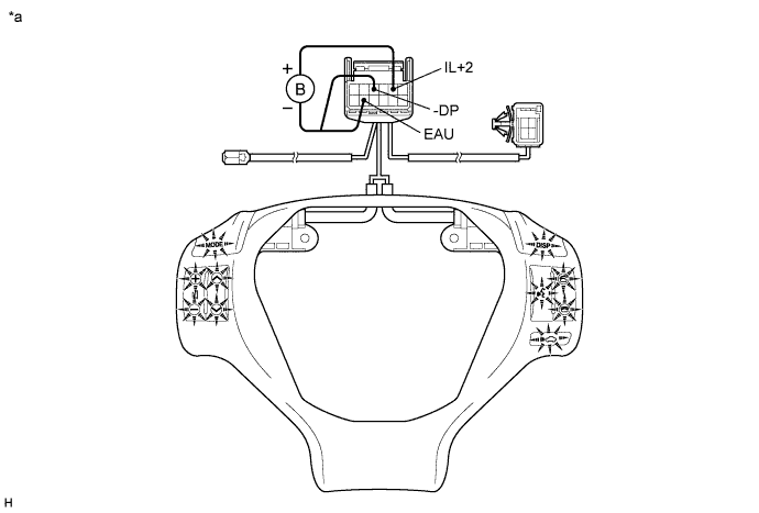
Measure the resistance according to the value(s) in the table below.
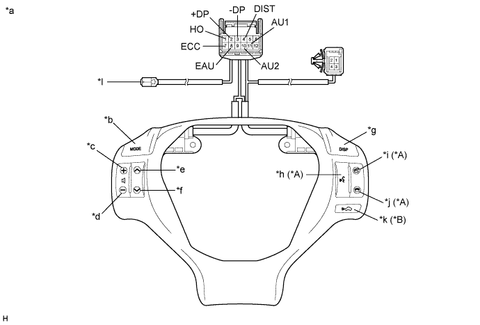
- Standard Resistance:
Tester Connection Condition Specified Condition 1 (HO) - Terminal-A Always Below 1 Ω 4 (DIST) - 7 (ECC) No switch pushed 95 to 105 kΩ Distance control switch pushed Below 2.5 Ω 2 (+DP) - 3 (-DP) No switch pushed 95 to 105 kΩ DISP switch pushed Below 2.5 Ω 11 (AU1) - 8 (EAU) No switch pushed 95 to 105 kΩ Seek+ switch pushed Below 2.5 Ω Seek- switch pushed 313 to 345 Ω Volume+ switch pushed 950 to 1050 Ω Volume- switch pushed 2955 to 3265 Ω 10 (AU2) - 8 (EAU) No switch pushed 95 to 105 kΩ MODE switch pushed Below 2.5 Ω Voice switch pushed*1 2955 to 3265 Ω On hook switch pushed*1 313 to 345 Ω Off hook switch pushed*1 950 to 1050 Ω
- *1: w/ Telephone Microphone Assembly
- HINT:
- If the result is not as specified, replace the steering pad switch assembly.
| *A | w/ Telephone Microphone Assembly | *B | w/ Dynamic Radar Cruise Control System |
| *a | Component without harness connected (Steering Pad Switch Assembly) | *b | MODE |
| *c | Volume+ | *d | Volume- |
| *e | Seek+ | *f | Seek- |
| *g | DISP | *h | Voice |
| *i | Off Hook | *j | On Hook |
| *k | Distance Control | *l | Terminal-A |