 |
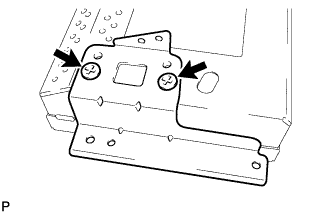
Install the multi-display controller bracket A with the 2 screws.
MULTI-DISPLAY > REASSEMBLY |
| 1. INSTALL MULTI-DISPLAY |
| 2. INSTALL MULTI-DISPLAY CONTROLLER BRACKET A |
|
Install the multi-display controller bracket A with the 2 screws.
| 3. INSTALL MULTI-DISPLAY CONTROLLER BRACKET B |
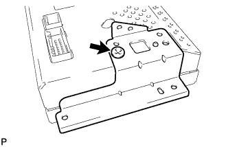 |
Install the multi-display controller bracket B with the screw.
| 4. INSTALL NO. 2 EARTH WIRE |
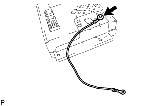 |
Install the No. 2 earth wire with the screw.
| 5. INSTALL MULTI-MEDIA MODULE WIRE |
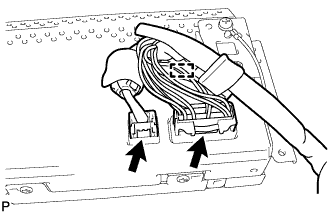 |
Engage the clamp and install the multi-media module wire.
Connect the 2 connectors.
| 6. INSTALL MULTI-DISPLAY ASSEMBLY |
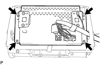 |
Install the multi-display assembly with the 4 screws.
| 7. INSTALL MULTI-DISPLAY CONTROLLER SUB-ASSEMBLY |
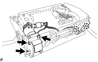 |
Install the multi-display controller sub-assembly with the 3 screws.
Engage the 2 claws and clamp.
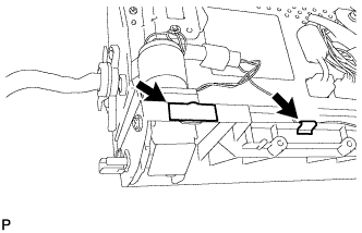 |
Install the new 2 tapes.
| 8. INSTALL UPPER INSTRUMENT CLUSTER FINISH PANEL |
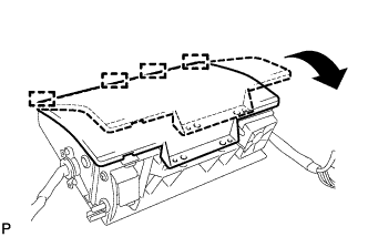 |
Engage the 4 guides and temporarily install the upper instrument cluster finish panel as shown in the illustration.
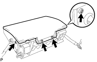 |
Install the upper instrument cluster finish panel with the 4 screws.
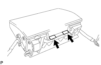 |
Install the 2 new tapes.
| 9. INSTALL INSTRUMENT PANEL REGISTER CONTROL GEAR |
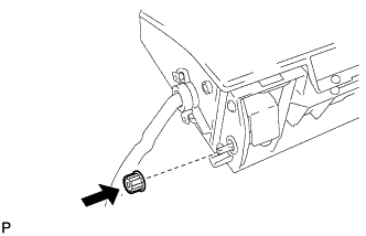 |
Install the instrument panel register control gear.
| 10. INSTALL NO. 2 INSTRUMENT PANEL FINISH PANEL RETAINER |
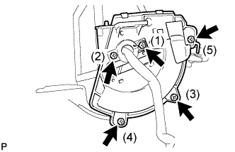 |
Install the No. 2 instrument panel finish panel retainer and No. 1 instrument panel finish panel retainer with the 5 screws.
| 11. INSTALL NO. 3 INSTRUMENT PANEL FINISH PANEL RETAINER |
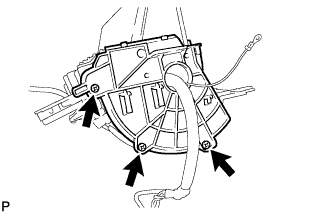 |
Install the No. 3 instrument panel finish panel retainer with the 3 screws.
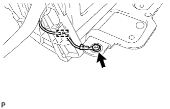 |
Engage the clamp and install the screw.
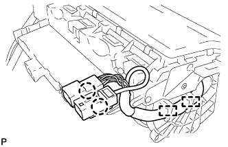 |
Engage the 2 clamps and connect the 2 claws.
| 12. INSTALL SENSOR WIRE |
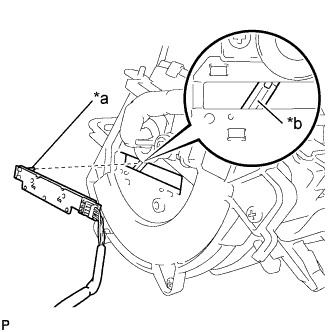 |
Align the pin of the sensor wire with the groove of the center instrument cluster finish panel assembly, and then install the sensor wire.
| *a | Pin |
| *b | Groove |
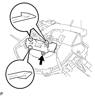 |
Engage the 3 claws.
Install the sensor wire cover with the screw.
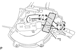 |
Engage the 2 clamps.
| *1 | Tape |
Using tape, secure the wire harness at the position shown in the illustration.
| 13. INSTALL INSTRUMENT CLUSTER FINISH PANEL COVER |
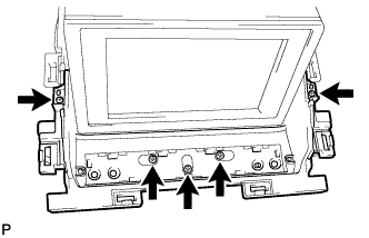 |
Install the instrument cluster finish panel cover with the 5 screws.
| 14. INSTALL DISPLAY MODULE BOARD |
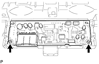 |
Install the display module board with the 2 screws.
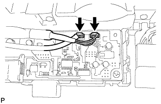 |
Connect the 2 connectors.
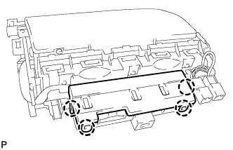 |
Engage the 4 claws to install the lower center instrument cover.