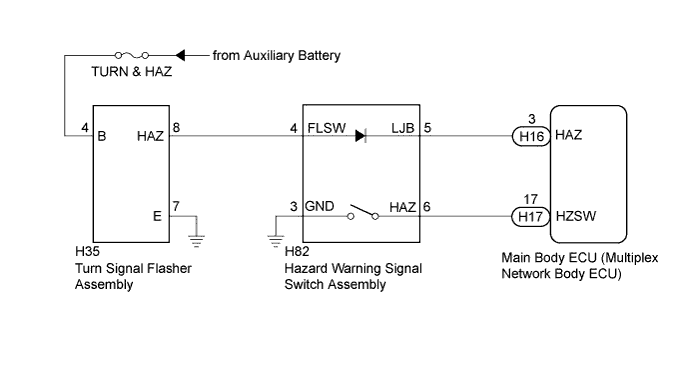
LIGHTING SYSTEM > Hazard Warning Switch Circuit |
| 1.READ VALUE USING INTELLIGENT TESTER |
Connect the intelligent tester to the DLC3.
Turn the power switch on (IG).
Turn the intelligent tester on.
Enter the following menus: Body / Main Body / Data List.
Read the display on the intelligent tester.
| Tester Display | Measurement Item/Range | Normal Condition | Diagnostic Note |
| Hazard Switch | Hazard switch signal/ON or OFF | ON: Hazard switch on OFF: Hazard switch off | - |
|
| ||||
| OK | |
 |
| 2.PERFORM ACTIVE TEST USING INTELLIGENT TESTER |
Connect the intelligent tester to the DLC3.
Turn the power switch on (IG).
Turn the intelligent tester on.
Enter the following menus: Body / Main Body / Active Test.
Check that the hazard lights illuminate.
| Tester Display | Test Part | Control Range | Diagnostic Note |
| Hazard | Hazard warning lights | ON/OFF | - |
|
| ||||
| OK | ||
 | ||
| ||
| 3.INSPECT HAZARD WARNING SIGNAL SWITCH ASSEMBLY |
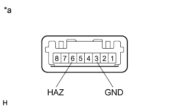 |
Remove the hazard warning signal switch assembly (Click here).
Measure the resistance according to the value(s) in the table below.
| Tester Connection | Switch Condition | Specified Condition |
| 6 (HAZ) - 3 (GND) | Hazard switch on | Below 1 Ω |
| 6 (HAZ) - 3 (GND) | Hazard switch off | 10 kΩ or higher |
| *a | Component without harness connected (Hazard Warning Signal Switch Assembly) |
|
| ||||
| OK | |
|
| 4.CHECK HARNESS AND CONNECTOR (HAZARD WARNING SIGNAL SWITCH - MAIN BODY ECU) |
Disconnect the H17 main body ECU (multiplex network body ECU) connector.
Measure the resistance according to the value(s) in the table below.
| Tester Connection | Condition | Specified Condition |
| H82-6 (HAZ) - H17-17 (HZSW) | Always | Below 1 Ω |
| H82-6 (HAZ) - Body ground | Always | 10 kΩ or higher |
| H82-3 (GND) - Body ground | Always | Below 1 Ω |
|
| ||||
| OK | ||
| ||
| ||
| 5.CHECK HARNESS AND CONNECTOR (TURN & HAZ FUSE - TURN SIGNAL FLASHER ASSEMBLY) |
Disconnect the H35 turn signal flasher assembly connector.
Measure the voltage according to the value(s) in the table below.
| Tester Connection | Condition | Specified Condition |
| H35-4 (B) - Body ground | Always | 11 to 14 V |
Measure the resistance according to the value(s) in the table below.
| Tester Connection | Condition | Specified Condition |
| H35-7 (E) - Body ground | Always | Below 1 Ω |
|
| ||||
| OK | |
|
| 6.INSPECT TURN SIGNAL FLASHER ASSEMBLY |
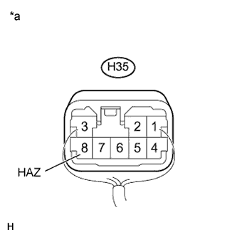 |
Reconnect the H35 turn signal flasher assembly connector.
Measure the voltage according to the value(s) in the table below.
| Tester Connection | Switch Condition | Specified Condition |
| H35-8 (HAZ) - Body ground | Hazard switch off | 9 V or higher |
| H35-8 (HAZ) - Body ground | Hazard switch on | Below 1 V |
| *a | Component without harness connected (Turn Signal Flasher Assembly) |
| Result | Proceed to |
| NG (when the hazard switch on) | A |
| NG (when the hazard switch off) | B |
| OK | B |
|
| ||||
| A | |
|
| 7.CHECK HARNESS AND CONNECTOR (TURN SIGNAL FLASHER - HAZARD WARNING SIGNAL SWITCH ASSEMBLY) |
Disconnect the H35 turn signal flasher assembly connector.
Disconnect the H82 hazard warning signal switch assembly connector.
Measure the resistance according to the value(s) in the table below.
| Tester Connection | Condition | Specified Condition |
| H35-8 (HAZ) - H82-4 (FLSW) | Always | Below 1 Ω |
| H35-8 (HAZ) - Body ground | Always | 10 kΩ or higher |
|
| ||||
| OK | |
|
| 8.CHECK HARNESS AND CONNECTOR (HAZARD WARNING SIGNAL SWITCH ASSEMBLY - MAIN BODY ECU) |
Disconnect the H16 main body ECU (multiplex network body ECU) connector.
Measure the resistance according to the value(s) in the table below.
| Tester Connection | Condition | Specified Condition |
| H82-5 (LJB) - H16-3 (HAZ) | Always | Below 1 Ω |
| H82-5 (LJB) - Body ground | Always | 10 kΩ or higher |
|
| ||||
| OK | |
|
| 9.INSPECT HAZARD WARNING SIGNAL SWITCH ASSEMBLY |
Reconnect the H35 turn signal flasher assembly connector.
Reconnect the H82 hazard warning signal switch assembly connector.
Reconnect the H16 main body ECU (multiplex network body ECU) connector.
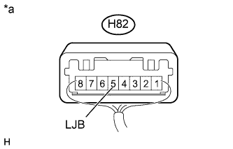 |
Measure the voltage according to the value(s) in the table below.
| Tester Connection | Switch Condition | Specified Condition |
| H82-5 (LJB) - Body ground | Power switch off | 11 to 14 V |
| *a | Component with harness connected (Hazard Warning Signal Switch Assembly) |
|
| ||||
| OK | ||
| ||
| ||

