Home Audio/Visual/Telematics PARK ASSIST / MONITORING CLEARANCE SONAR MAIN SWITCH

CLEARANCE SONAR MAIN SWITCH > INSPECTION

for Preparation Click here


1. INSPECT BACK SONAR OR CLEARANCE SONAR SWITCH ASSEMBLY


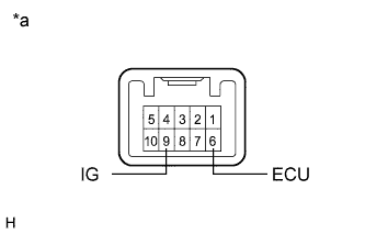
    E197324E06
  1. Measure the resistance according to the value(s) in the table below.

    Standard Resistance:
    Tester Connection
    Switch Condition
    Specified Condition
    9 (IG) - 6 (ECU)
    Clearance sonar main switch is pushed
    Below 1 Ω
    9 (IG) - 6 (ECU)
    Clearance sonar main switch is not pushed
    10 kΩ or higher

    Text in Illustration 
    *a
    Component without harness connected
    (Back Sonar or Clearance Sonar Switch Assembly)
    If the result is not as specified, replace the back sonar or clearance sonar switch assembly.


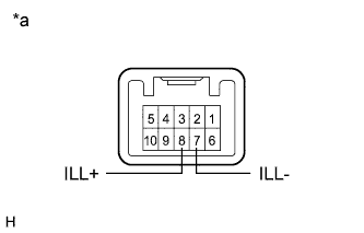
  1. Check that the switch illuminates.


      E197324E05
    1. Apply auxiliary battery voltage to the back sonar or clearance sonar switch assembly and check that the switch illuminates.

      OK:
      Tester Connection
      Specified Condition
      Auxiliary battery positive (+) → Terminal 8
      Auxiliary battery negative (-) → Terminal 7
      Illuminates

      Text in Illustration 
      *a
      Component without harness connected
      (Back Sonar or Clearance Sonar Switch Assembly)
      If the result is not as specified replace the back sonar or clearance sonar switch assembly.