Home General INTRODUCTION REPAIR INSTRUCTION

REPAIR INSTRUCTION > CUSTOMIZE PARAMETERS


1. CUSTOMIZE LEXUS PARKING ASSIST-SENSOR SYSTEM
  1. Customizing with the intelligent tester

    NOTICE:
    1. When the customer requests a change in a function, first make sure that the function can be customized.
    2. Be sure to make a note of the current settings before customizing.
    3. When troubleshooting a function, first make sure that the function is set to the default setting.


    1. Connect the intelligent tester to the DLC3.

    2. Turn the power switch on (IG).

    3. Turn the LEXUS parking assist-sensor system on.

    4. Enter the following menus: Body / Clearance Sonar / Utility / Customize Setting.

    5. Select the setting by referring to the table below.

      Warning 
      Display
      Default
      Content
      Setting
      Relevant ECU
      Rr Sensor Onset Range
      Wide
      Sets the buzzer activation range for the rear center sensors.
      Narrow or Wide
      1. Narrow: 600 mm (1.97 ft.)
      2. Wide: 1500 mm (4.92 ft.)
      Clearance warning ECU assembly
      Keep Sense Buzzer
      Avail
      Sounds the buzzer when the distance between the vehicle and obstacle does not change for more than 3 seconds.
      Not Avail or Avail
      1. Not Avail: Not Available
      2. Avail: Available
      Clearance warning ECU assembly
      Fr & Rr Buzzer Volume
      M2
      Changes the buzzer volume setting.
      L, M1, M2, M3 or H
      1. L: Low volume
      2. M1: Medium low volume
      3. M2: Medium volume
      4. M3: Medium high volume
      5. H: High volume
      Clearance warning ECU assembly

      Sensor 
      Display
      Default
      Content
      Setting
      Relevant ECU
      Sensor Condition N
      Avail
      Makes the front sensors available when neutral (N) has been selected.
      Not Avail or Avail
      1. Not Avail: Not Available
      2. Avail: Available
      Clearance warning ECU assembly
      Reverse Range Front Sensor
      F
      Changes the operation setting for the front sensors when reverse (R) has been selected.
      F or F Stop
      1. F: Front sensors are available
      2. F Stop: Front sensors are not available
      Clearance warning ECU assembly
      Non P/R Range Rear Sensor
      R Stop
      Changes the operation setting for the rear sensors when a shift state other than park (P) or reverse (R) has been selected.
      R, Rcrn or R Stop
      1. R: All rear sensors are available
      2. Rcrn: Rear corner sensors are available
      3. R Stop: All rear sensors are not available
      Clearance warning ECU assembly

      Display 
      Display
      Default
      Content
      Setting
      Relevant ECU
      Display Mode
      All
      The display mode setting (when the LEXUS parking assist-sensor system is normal).
      All or Undisp
      Clearance warning ECU assembly

  1. Customizing with Multi-display

    NOTICE:
    1. When the customer requests a change in a function, first make sure that the function can be customized.
    2. Be sure to make a note of the current settings before customizing.
    3. When troubleshooting a function, first make sure that the function is set to the default setting.


    1. Turn the power switch on (IG).

    2. Turn the LEXUS parking assist-sensor system on.

    3. Enter the following menus: Setup / Vehicle / LEXUS park assist.

    4. Select the setting by referring to the table below.

      Display
      Default
      Content
      Setting
      Relevant ECU
      Alert volume
      3
      Sets the buzzer activation range for the rear center sensors.
      1, 2, 3, 4 or 5
      1. 1: Low volume
      2. 2: Medium low volume
      3. 3: Medium volume
      4. 4: Medium high volume
      5. 5: High volume
      Clearance warning ECU assembly
      Display
      On
      The display mode setting (when the LEXUS parking assist-sensor system is normal).
      On or Off
      Clearance warning ECU assembly
      Distance
      Wide
      Sets the buzzer activation range for the rear center sensors.
      Narrow or Wide
      1. Narrow: 600 mm (1.97 ft.)
      2. Wide: 1500 mm (4.92 ft.)
      Clearance warning ECU assembly


2. CUSTOMIZE POWER DOOR LOCK CONTROL SYSTEM

HINT:
The following items can be customized.

NOTICE:
  1. When the customer requests a change in a function, first make sure that the function can be customized.
  2. Be sure to make a note of the current settings before customizing.
  3. When troubleshooting a function, first make sure that the function is set to the default setting.

  1. Customizing with the intelligent tester.

    1. Connect the intelligent tester to the DLC3.

    2. Turn the power switch on (IG).

    3. Turn the intelligent tester on.

    4. Enter the following menus: Body / Main Body / Utility / Customize / Door Lock.

    5. Select the setting by referring to the table below.

      Display
      Default
      Content
      Setting
      Relevant ECU
      Unlock Key Twice
      ON*1
      OFF*2
      Function that unlocks only the driver door when the driver door key cylinder is turned to unlock once, and unlock all doors when it is turned to unlock twice. For the OFF setting, turning it once unlocks all doors.
      ON or OFF
      Main body ECU (Multiplex network body ECU)
      Auto Lock
      ON*2
      OFF*1
      Function that locks all doors when the vehicle speed reaches a certain level.
      ON or OFF
      Main body ECU (Multiplex network body ECU)
      Auto Lock/Shift
      ON*1
      OFF*2
      Function that locks all doors when the shift lever is moved to select another shift state with park (P) selected, the power switch on (READY) and all doors closed.
      ON or OFF
      Main body ECU (Multiplex network body ECU)
      Auto Unlock/Shift
      ON*1
      OFF*2
      Function that unlocks all doors when the P position switch (transmission shift main switch) is pushed with a shift state other than park (P) selected and the power switch on (READY).
      ON or OFF
      Main body ECU (Multiplex network body ECU)
      All Unlock/Open-Close
      OFF
      Function that unlocks the other doors when the driver door is opened within 10 seconds after the power switch is turned off.
      ON or OFF
      Main body ECU (Multiplex network body ECU)
      *1: for G.C.C. countries, Australia and New Zealand
      *2: except G.C.C. countries, Australia and New Zealand

  1. Customizing with the combination meter assembly

    HINT:
    1. Press and hold DISP switch (steering pad switch assembly) when entering an item.
    2. Briefly press DISP switch (steering pad switch assembly) when selecting an item.


    1. Turn the power switch on (IG).

    2. Enter the following menus: Settings / Vehicle Settings.

    3. Select the setting by referring to the table below.

      Display
      Default
      Content
      Setting
      Relevant ECU
      SPEED SENSITIVE AUTO. LOCK
      ON*2
      OFF*1
      Function that locks all doors when the vehicle speed reaches a certain level.
      ON or OFF
      Main body ECU (Multiplex network body ECU)
      SHIFT-LINKED AUTOMATIC LOCK
      ON*1
      OFF*2
      Function that locks all doors when the shift lever is moved to select another shift state with park (P) selected, the power switch on (READY) and all doors closed.
      ON or OFF
      Main body ECU (Multiplex network body ECU)
      SHIFT-LINKED AUTOMATIC UNLOCK
      ON*1
      OFF*2
      Function that unlocks all doors when the P position switch (transmission shift main switch) is pushed with a shift state other than park (P) selected and the power switch on (READY).
      ON or OFF
      Main body ECU (Multiplex network body ECU)
      DRIVER DOOR-LINKED UNLOCK
      ON*1
      OFF*2
      Function that unlocks the other doors when the driver door is opened within 10 seconds after the power switch is turned off.
      ON or OFF
      Main body ECU (Multiplex network body ECU)
      *1: for G.C.C. countries, Australia and New Zealand
      *2: except G.C.C. countries, Australia and New Zealand

    4. Press and hold DISP switch (steering pad switch assembly).

    5. The setting completion screen will be displayed.

    6. Return to the item selection screen.


3. CUSTOMIZE WIRELESS DOOR LOCK CONTROL SYSTEM

HINT:
The following items can be customized.

NOTICE:
  1. When the customer requests a change in a function, first make sure that the function can be customized.
  2. Be sure to make a note of the current settings before customizing.
  3. When troubleshooting a function, first make sure that the function is set to the default setting.

  1. Customizing with the intelligent tester.

    1. Connect the intelligent tester.

    2. Turn the power switch on (IG).

    3. Turn the intelligent tester on.

    4. Enter the following menus: Body / Main Body / Utility / Customize / Wireless Door Lock.

    5. Select the setting by referring to the table below.

      Display
      Default
      Content
      Setting
      Relevant ECU
      Wireless Control
      ON
      Function that turns wireless door lock/ON or OFF
      ON or OFF
      Main body ECU (Multiplex network body ECU)
      Hazard Answer Back
      ON
      When the doors are locked by wireless operation, the hazard warning lights flash once.
      When the doors are unlocked by wireless operation, the hazard warning lights flash twice.
      ON or OFF
      Main body ECU (Multiplex network body ECU)
      Open Door Warning
      ON
      The buzzer sounds when lock is pressed when any of the doors are ajar.
      ON or OFF
      Main body ECU (Multiplex network body ECU)
      Unlock 2 Operation
      ON*1
      OFF*2
      Function that unlocks driver door when unlock switch on electrical key transmitter is pressed once, and unlocks all doors when pressed twice. If setting is OFF, pressing unlock switch once makes all doors unlock.
      ON or OFF
      Main body ECU (Multiplex network body ECU)
      Panic Function*3
      ON
      Function to operate theft deterrent system by continuously pressing panic switch on electrical key transmitter for 0.8 seconds
      ON or OFF
      Main body ECU (Multiplex network body ECU)
      Auto Lock Time
      30 s
      Function that regulates the interval between unlocking and automatic relocking of doors
      30 s, 60 s or 120 s
      Main body ECU (Multiplex network body ECU)
      Wireless Buzzer Resp*3
      ON
      Wireless door lock buzzer response/ON or OFF
      ON or OFF
      Main body ECU (Multiplex network body ECU)
      P/W Ope buzzer
      ON
      Wireless power window buzzer response/ON or OFF
      ON or OFF
      Main body ECU (Multiplex network body ECU)
      Wireless Buzzer Vol
      Level7
      Wireless door lock buzzer volume
      Level7, Level6, Level5, Level4, Level3, Level2, Level1 or Level0
      Main body ECU (Multiplex network body ECU)
      *1: for G.C.C. countries, Australia and New Zealand
      *2: except G.C.C. countries, Australia and New Zealand
      *3: except Europe

  1. Customizing with the combination meter assembly

    HINT:
    1. Press and hold DISP switch (steering pad switch assembly) when entering an item.
    2. Briefly press DISP switch (steering pad switch assembly) when selecting an item.


    1. Turn the power switch on (IG).

    2. Enter the following menus: Settings / Vehicle Settings.

    3. Select the setting by referring to the table below.

      Display
      Default
      Content
      Setting
      Relevant ECU
      REMOTE 2-PRESS UNLOCK
      ON*1
      OFF*2
      Function that unlocks the driver door when the unlock switch on the electrical key transmitter is pressed once, and unlocks all doors when pressed twice. If the setting is OFF, pressing the unlock switch once makes all doors unlock.
      ON or OFF
      Main body ECU (Multiplex network body ECU)
      AUTO. RELOCK TIME ADJUSTMENT
      30 s
      Function that regulates the interval between unlocking and automatic relocking of doors.
      30 s, 60 s or 120 s
      Main body ECU (Multiplex network body ECU)
      LOCK/UNLOCK ANSWER BACK
      ON
      When the doors are locked by wireless operation, the hazard warning lights flash once.
      When the doors are unlocked by wireless operation, the hazard warning lights flash twice.
      ON or OFF
      Main body ECU (Multiplex network body ECU)
      LOCK FEEDBACK VOLUME
      7
      Wireless door lock buzzer volume
      0, 1, 2, 3, 4, 5, 6 or 7
      Main body ECU (Multiplex network body ECU)
      *1: for G.C.C. countries, Australia and New Zealand
      *2: except G.C.C. countries, Australia and New Zealand

    4. Press and hold DISP switch (steering pad switch assembly).

    5. The setting completion screen will be displayed.

    6. Return to the item selection screen.


4. CUSTOMIZE ENTRY AND START SYSTEM (for Entry Function)

HINT:
The following items can be customized.

NOTICE:
  1. When the customer requests a change in a function, first make sure that the function can be customized.
  2. Record the current settings before customizing.

  1. Customizing with the intelligent tester

    1. Connect the intelligent tester to the DLC3.

    2. Turn the power switch on (IG).

    3. Turn the intelligent tester on.

    4. Enter the following menus: Body / Main Body or Entry & Start / Utility / Customize / Wireless Door Lock, Entry & Start or Warning.

    5. Select the setting by referring to the table below.

      Display
      Default
      Content
      Setting
      Relevant ECU
      Wireless Buzzer Resp*2
      ON
      Function that buzzer answer back when entry lock or unlock operation is performed.
      ON or OFF
      Main body ECU (Multiplex network body ECU)
      Park Wait Time (Waiting time to permit unlocking door after locking)
      2.5s
      Function that sets the period of time (lock confirmation time) that the door is prevented from being unlocked by operating the front door outside handle assembly after an entry lock operation is performed.
      0.5s, 1.5s, 2.5s or 5s
      Certification ECU (smart key ECU assembly)
      Ignition Available Area
      (Entry ignition available area)
      All
      Function that sets the area that the key must be in before the power switch can be operated.
      Front or All
      Certification ECU (smart key ECU assembly)
      Back Door Opening Operation
      Long
      Function that opens the back door when the driver has the key and presses back door opener switch assembly (opener switch)
      Long, Twice or OFF
      Certification ECU (smart key ECU assembly)
      Key Low Battery Warning (Warn when key battery becomes weak)
      ON
      Enables or disables the sounding of the buzzer when the key battery is low and the power switch is turned off after being on (IG) for 20 minutes or more.
      ON or OFF
      Certification ECU (smart key ECU assembly)
      Door Unlock Mode
      All*1/Driver*2
      Function that chooses the doors to be operated by entry unlock operation
      All or Driver
      Certification ECU (smart key ECU assembly)
      Auto Entry Cancel SW
      OFF
      Function that enables or disables the entry and start system.
      ON or OFF
      Certification ECU (smart key ECU assembly)
      Touch Activation Over Threshold*2
      Active*4/Not Active*3
      The function that limits the consecutive entry lock operation to only 2 times can be changed between Active and Not Active. When in Not Active mode, there is no limit for the number of times that the consecutive entry lock operation can be performed.
      Active or Not Active
      Certification ECU (smart key ECU assembly)

      1. *1: for Europe
      2. *2: except for Europe
      3. *3: for Australia
      4. *4: for G. C. C

  1. Customizing with the Combination meter assembly

    HINT:
    1. Press and hold the DISP (steering pad switch assembly) when entering an item.
    2. Briefly press the DISP (steering pad switch assembly) when selecting an item.


    1. Turn the power switch on (IG).

    2. Enter the following menus: Settings / Vehicle Settings

    3. Select the setting by referring to the table below

      Display
      Default
      Content
      Setting
      Relevant ECU
      SELECT DOORS TO UNLOCK
      ALL*1
      DRIVER*2
      Function that chooses the doors to be operated by entry unlock operation
      ALL or DRIVER
      Certification ECU (smart key ECU assembly)
      ENTRY AND START SYSTEM
      ON
      Function that enables or disables the entry and start system.
      ON or OFF
      Certification ECU (smart key ECU assembly)

      1. *1: for Europe
      2. *2: except for Europe

    4. Press and hold the DISP (steering pad switch assembly).

    5. The setting completion screen will be displayed.

    6. Return to the item selection screen.


  1. Entry unlock mode switching function

    NOTICE:
    Because the key (for card type) does not have a wireless transmitter function, it cannot be used to change the entry unlock mode.


    1. The following entry unlock modes can be selected when using the entry unlock mode switching function.

      1. All door unlock mode: When the sensor of a front door outside handle assembly is touched, an entry unlock operation is performed simultaneously for all doors.
      2. Driver door unlock mode: When the sensor of the front door outside handle assembly is touched, an entry unlock operation is performed for the driver door only. If any other door handle is touched, an entry unlock operation is performed simultaneously for all doors.


    2. When customizing through manual operation:

      1. Turn the power switch off.
      2. Intrusion sensor is off (Intrusion sensor cancel switch is on).
      3. Check that the LED of the key is not illuminated, and then press and hold the lock and unlock buttons of the key for 5 seconds or more while the key is in the actuation area.
      4. Check the current setting.

        HINT:
        1. The mode changes from all door unlock mode to driver door unlock mode and then back to all door unlock mode.
        2. The answer-back (wireless buzzer, buzzer in the combination meter assembly) performed for each mode is indicated in the table below.

          Currently Selected Mode
          Answer-back (Wireless Buzzer)
          Answer-back (Buzzer in Combination Meter Assembly)
          All door unlock mode
          Buzzer sounds twice (short beeps)
          Buzzer sounds once ("pong" sound)
          Driver door unlock mode
          Buzzer sounds 3 times (short beeps)
          Buzzer sounds once ("pong" sound)

      5. Release the lock and unlock buttons of the key.
      6. Check that the LED of the key is not illuminated, and then press and hold the lock and unlock buttons of the key for 5 seconds or more to change the mode.

        HINT:
        Repeat the procedure as necessary to select the desired mode.

      7. Unlock the doors with the wireless operation, and then open any door
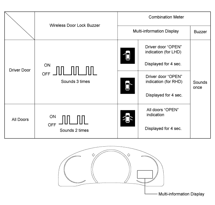

      B265895E03

  1. Entry cancel function

    NOTICE:
    Because the key (for card type) does not have a wireless transmitter function, it cannot be used to change the entry unlock mode.

    HINT:
    While the entry and start system is canceled, it is possible to lock and unlock the doors with the wireless operation, and the start system can be operated by holding the key against the power switch.


    1. The following functions are disabled when the entry and start system is canceled.

      1. Entry unlock/lock functions
      2. Push start function
      3. Key lock-in prevention function
      4. Entry warning functions

    2. When canceling the system through manual operation:

      1. Make sure the following conditions are met:
        1. The power switch is off.
        2. The driver door is closed.
        3. The driver door is unlocked.
      2. Press the unlock button of the key.
      3. Open the driver door within 5 seconds of completing the step above (driver door: closed at beginning of step → opened).
      4. With the driver door open, press the unlock button of the key 2 times within 5 seconds of completing the step above.

        NOTICE:
        If the driver door is closed before or while pressing the unlock button, the entry cancel setting mode will end.

      5. Close and open the driver door twice within 30 seconds of completing the above step (driver door: open at beginning of step → closed → opened → closed → opened).
      6. With the driver door open, press the unlock button of the key 2 times within 30 seconds of completing the step above.

        NOTICE:
        If the driver door is closed before or while pressing the unlock button, the entry cancel setting mode will end.

      7. Close and open the driver door within 30 seconds of completing the step above (driver door: open at beginning of step → closed → opened).
      8. Close the driver door within 5 seconds of completing the above step.
      9. Check that the wireless buzzer sounds twice (short beeps) to confirm that the entry and start system has been canceled.

    3. Perform the following procedure to restore the entry and start system to the active state from the canceled state.

      1. Perform the procedures to cancel the entry and start system again.
      2. Check that the wireless buzzer sounds once (short beep) to confirm that the entry and start system has been restored to the active state.

        HINT:
        1. The system changes between the canceled state and the active state each time the procedure to cancel the system through manual operation is performed.
        2. The buzzer sounds twice when the system changes from the active state to the canceled state, and sounds once when the system changes from the canceled state to the active state.


5. CUSTOMIZE ENTRY AND START SYSTEM (for Start Function)

HINT:
The following items can be customized.

NOTICE:
  1. When the customer requests a change in a function, first make sure that the function can be customized.
  2. Record the current settings before customizing.

  1. Customizing with the intelligent tester

    1. Connect the intelligent tester to the DLC3.

    2. Turn the power switch on (IG).

    3. Turn the intelligent tester on.

    4. Body / Entry&Start / Utility / Customize / Entry&Start or Warning

    5. Select the setting by referring to the table below.

      Display
      Default
      Content
      Setting
      Relevant ECU
      Auto Entry Cancel SW
      OFF
      Function that enables or disables the entry and start system.
      ON or OFF
      Certification ECU (smart key ECU assembly)
      Ignition Available Area
      (Entry ignition available area)
      All
      Function that sets the area that the key must be in before the power switch can be operated.
      Front or All
      Certification ECU (smart key ECU assembly)
      Key Low Battery Warning (Warn when key battery becomes weak)
      ON
      Enables or disables the sounding of the buzzer when the key battery is low and the power switch is turned off after being on (IG) for 20 minutes or more.
      ON or OFF
      Certification ECU (smart key ECU assembly)

  1. Customizing with the Combination meter assembly

    HINT:
    1. Press and hold the DISP (steering pad switch assembly) when entering an item.
    2. Briefly press the DISP (steering pad switch assembly) when selecting an item.


    1. Turn the power switch on (IG).

    2. Enter the following menus: Settings / Vehicle Settings.

    3. Select the setting by referring to the table below.

      Display
      Default
      Content
      Setting
      Relevant ECU
      ENTRY AND START SYSTEM
      ON
      Function that enables or disables the entry and start system.
      ON or OFF
      Certification ECU (smart key ECU assembly)

    4. Press and hold the DISP (steering pad switch assembly).

    5. The setting completion screen will be displayed.

    6. Return to the item selection screen.

  1. Entry cancel function (manual operation)

    NOTICE:
    Because the key (for card type) does not have a wireless transmitter function, it cannot be used to change the entry unlock mode.

    HINT:
    While the entry and start system is canceled, it is possible to lock and unlock the doors with the wireless operation, and the start system can be operated by holding the key against the power switch.


    1. The following functions are disabled when the entry and start system is canceled.

      1. Entry unlock/lock functions
      2. Push-button start function
      3. Key lock-in prevention function
      4. Entry warning functions

    2. When canceling the system through manual operation:

      1. Make sure the following conditions are met:
        1. The power switch is off.
        2. The driver door is closed.
        3. The driver door is unlocked.
      2. Press the unlock button of the key.
      3. Open the driver door within 5 seconds of completing the step above (driver door: closed at beginning of step → opened).
      4. With the driver door open, press the unlock button of the key 2 times within 5 seconds of completing the step above.

        NOTICE:
        If the driver door is closed before or while pressing the unlock button, the entry cancel setting mode will end.

      5. Close and open the driver door twice within 30 seconds of completing the above step (driver door: open at beginning of step → closed → opened → closed → opened).
      6. With the driver door open, press the unlock button of the key 2 times within 30 seconds of completing the step above.

        NOTICE:
        If the driver door is closed before or while pressing the unlock button, the entry cancel setting mode will end.

      7. Close and open the driver door within 30 seconds of completing the step above (driver door: open at beginning of step → closed → opened).
      8. Close the driver door within 5 seconds of completing the above step.
      9. Check that the wireless buzzer sounds twice (short beeps) to confirm that the entry and start system has been canceled.

    3. Perform the following procedure to restore the entry and start system to the active state from the canceled state.

      1. Perform the procedures to cancel the entry and start system again.
      2. Check that the wireless buzzer sounds once (short beep) to confirm that the entry and start system has been restored to the active state.

        HINT:
        1. The system changes between the canceled state and the active state each time the procedure to cancel the system through manual operation is performed.
        2. The buzzer sounds twice when the system changes from the active state to the canceled state, and sounds once when the system changes from the canceled state to the active state.


6. CUSTOMIZE PUSH-BUTTON START SYSTEM

HINT:
The following items can be customized.

NOTICE:
  1. When the customer requests a change in a function, first make sure that the function can be customized.
  2. Record the current settings before customizing.

  1. Customizing with the intelligent tester

    1. Connect the intelligent tester to the DLC3.

    2. Turn the power switch on (IG).

    3. Turn the intelligent tester on.

    4. Enter the following menus: Body / Entry&Start / Utility / Customize / Entry&Start or Warning.

    5. Select the setting by referring to the table below.

      Display
      Default
      Content
      Setting
      Relevant ECU
      Auto Entry Cancel SW
      OFF
      Function that enables or disables the push-button start system.
      ON or OFF
      Certification ECU (smart key ECU assembly)
      Ignition Available Area
      (Entry ignition available area)
      All
      Function that sets the area that the key must be in before the power switch can be operated.
      Front or All
      Key Low Battery Warning (Warn when key battery becomes weak)
      ON
      Enables or disables the sounding of the buzzer when the key battery is low and the power switch is turned off after being on (IG) for 20 minutes or more.
      ON or OFF

  1. Customizing with the Combination meter assembly

    HINT:
    1. Press and hold DISP (steering pad switch assembly) when entering an item.
    2. Briefly press DISP (steering pad switch assembly) when selecting an item.


    1. Turn the power switch on (IG).

    2. Enter the following menus: SETTINGS / VEHICLE SETTINGS

    3. Select the setting by referring to the table below

      Display
      Default
      Content
      Setting
      Relevant ECU
      ENTRY AND START SYSTEM
      ON
      Function that enables or disables the push-button start system.
      ON or OFF
      Certification ECU (smart key ECU assembly)

    4. Press and hold DISP (steering pad switch assembly).

    5. The setting completion screen will be displayed.

    6. Return to the item selection screen.

  1. Push-button start cancel function (manual operation)

    HINT:
    While the push-button start system is canceled, the push-button start system can be operated by holding the key against the power switch.


    1. The following functions are disabled when the push-button start system is canceled.

      1. Push-button start function
      2. Key lock-in prevention function
      3. Push-button start warning functions

    2. When canceling the system through manual operation:

      1. Make sure the following conditions are met:
        1. The power switch is off.
        2. The driver door is closed.
        3. The driver door is unlocked.
      2. Press the unlock button of the key.
      3. Open the driver door within 5 seconds of completing the step above (driver door: closed at beginning of step → opened).
      4. With the driver door open, press the unlock button of the key 2 times within 5 seconds of completing the step above.

        NOTICE:
        If the driver door is closed before or while pressing the unlock button, the push-button start cancel setting mode will end.

      5. Close and open the driver door twice within 30 seconds of completing the step above (driver door: open at beginning of step → closed → opened → closed → opened).
      6. With the driver door open, press the unlock button of the key 2 times within 30 seconds of completing the step above.

        NOTICE:
        If the driver door is closed before or while pressing the unlock button, the push-button start cancel setting mode will end.

      7. Close and open the driver door within 30 seconds of completing the step above (driver door: open at beginning of step → closed → opened)
      8. Close the driver door within 5 seconds of completing the step above.
      9. Check that the wireless buzzer sounds twice (short beeps) to confirm that the push-button start system has been canceled.

    3. Perform the following procedure to restore the push-button start system to the active state from the canceled state.

      1. Perform the procedures to cancel the push-button start system again.
      2. Check that the wireless buzzer sounds once (short beep) to confirm that the push-button start system has been restored to the active state.

        HINT:
        1. The system changes between the canceled state and the active state each time the procedure to cancel the system through manual operation is performed.
        2. The buzzer sounds twice when the system changes from the active state to the canceled state, and sounds once when the system changes from the canceled state to the active state.


7. CUSTOMIZE THEFT DETERRENT SYSTEM

HINT:
The following items can be customized.

NOTICE:
  1. When the customer requests a change in a function, first make sure that the function can be customized.
  2. Be sure to make a note of the current settings before customizing.
  3. When troubleshooting a function, first make sure that the function is set to the default setting.

  1. Customizing with the intelligent tester

    1. Connect the intelligent tester to the DLC3.

    2. Turn the power switch on (IG).

    3. Turn the intelligent tester on.

    4. Enter the following menus: Body / Main Body / Utility / Customize / Security

    5. Select the setting by referring to the table below.

      Display
      Default
      Content
      Setting
      Relevant ECU
      Panic Function*1
      ON
      This function operates the theft deterrent system when the panic switch is pressed and held for 0.8 seconds.
      ON or OFF
      Main Body ECU (Multiplex Network Body ECU)
      Security control with mechanism key*2
      OFF
      This function set to be able to release security alarm with the mechanism key
      ON or OFF
      Intrusion Win Opened
      NORMAL
      This function sets the sensitivity of the intrusion sensor when a door window is open.
      NORMAL or SENS

      1. *1: w/ Panic Switch
      2. *2: w/ Airbag Cut Off Switch


8. CUSTOMIZE LIGHTING SYSTEM (INT)
  1. Customizing with the intelligent tester

    HINT:
    The following items can be customized.

    NOTICE:
    1. When the customer requests a change in a function, first make sure that the function can be customized.
    2. Be sure to make a note of the current settings before customizing.
    3. When troubleshooting a function, first make sure that the function is set to the default setting.


    1. Connect the intelligent tester to the DLC3.

    2. Turn the power switch on (IG).

    3. Turn the intelligent tester on.

    4. Enter the following menus: Body / Main Body / Utility / Customize / Illuminated Entry.

    5. Select the setting by referring to the table below.

      Illuminated Entry 
      Tester Display
      Default
      Content
      Setting
      Relevant ECU
      Lighting Time
      15 s
      Changes the lighting time after closing all of the doors. (It will fade out immediately in case of turning the power switch from off to on (ACC or IG).)
      7.5 s, 15 s or 30 s
      Main body ECU (Multiplex network body ECU)
      I/L when ACC OFF
      ON
      Lights up the power switch illumination, front interior lights and rear interior light when the power switch is turned from on (ACC or IG) to off.
      ON or OFF
      I/L ON W/Door Key Unlock
      ON
      Lights up the power switch illumination, front interior lights and rear interior light when doors are unlocked using a mechanical key or door control transmitter.
      ON or OFF
      Room Light when Aprchd
      ON
      Lights up the power switch illumination, front interior lights, rear interior light and footwell lights when a key enters any actuation area around the doors.
      ON or OFF
      Inside Foot Light
      ON
      Lights up the footwell lights illumination.
      ON or OFF
      Center Console Spot Light
      ON
      Lights up the center console spot light when the power switch is turned on (ACC or IG).
      ON or OFF
      Light Control
      ON
      Dims (ON setting) or turns off (OFF setting) the footwell lights when all of the following conditions are met:
      1. The power switch is on (IG).
      2. The shift lever is moved to select a shift state other than park (P).
      3. All doors are closed.
      ON or OFF
      Interior Light Control
      ON
      Lights up the front interior lights, footwell lights and center console spot light when the illuminated entry function is operating.
      ON or OFF

  1. Customizing with the combination meter assembly

    HINT:
    1. Press and hold the DISP switch (steering pad switch assembly) when entering an item.
    2. Briefly press the DISP switch (steering pad switch assembly) when selecting an item.


    1. Turn the power switch on (IG).

    2. Enter the following menus: Settings / Vehicle Settings

    3. Select the setting by referring to the table below

      Display
      Default
      Content
      Setting
      Relevant ECU
      Int. Lights Off Adjustment
      15 sec.
      Changes the lighting time after closing all of the doors. (It will fade out immediately in case of turning the power switch from off to on (ACC or IG).)
      15 sec., 7.5 sec., 30 sec. or OFF
      Main body ECU (Multiplex network body ECU)

    4. Press and hold the DISP switch (steering pad switch assembly).

    5. The setting completion screen will be displayed.

    6. Return to the item selection screen.


9. CUSTOMIZE METER / GAUGE SYSTEM
  1. Customizing with the intelligent tester

    1. Connect the intelligent tester to the DLC3.

    2. Turn the power switch on (IG).

    3. Turn the intelligent tester on.

    4. Enter the following menus:

      1. for Warning: Customize Setting / Combination Meter / Warning.
      2. for Display: Customize Setting / Combination Meter / Display.

    5. Select the setting by referring to the table below.

      NOTICE:
      1. Be sure to record the current value before customizing.

      HINT:
      The following items can be customized using the intelligent tester.


      Warning 
      Tester Display
      Default
      Content
      Setting
      Relevant ECU
      Driver Side Seatbelt Warning Buzzer*1
      ON
      Function to turn on/off the seat belt warning buzzer
      ON or OFF
      Combination meter assembly
      Front Passenger Side Seatbelt Warning Buzzer*1
      ON
      Function to turn on/off the seat belt warning buzzer
      ON or OFF
      Combination meter assembly
      Rear Seatbelt Warning Buzzer*2
      ON
      Function to turn on/off the rear seat belt warning buzzer
      ON or OFF
      Combination meter assembly
      Reverse Buzzer
      Continual
      Function to change the type of the reverse warning buzzer
      Single or Continual
      Combination meter assembly
      1. *1: This setting is only valid for the buzzer which sounds at 20 km/h (12 mph) or more
      2. *2: w/ Rear Seat Belt Warning

  1. Customizing with the combination meter assembly

    HINT:
    1. Press and hold the DISP switch (steering pad switch assembly) when entering an item.
    2. Briefly pressed the DISP switch (steering pad switch assembly) when selecting an item.


    1. Turn the power switch on (IG).

    2. Select the following menus: SETTINGS / METER SETTING.

    3. Select the setting by referring to the table below.

      NOTICE:
      1. Be sure to record the current value before customizing.

      HINT:
      The following items can be customized operating the combination meter assembly.


      Meter Setting 
      Tester Display
      Default
      Content
      Setting
      Relevant ECU
      TACHO METER
      AUTO
      Function to change the tachometer setting
      AUTO, KEEP ON, OFF
      Combination meter assembly
      ECO LAMP
      ECO DRIVE SUPPORT
      Function to change the illumination level
      ECO DRIVE SUPPORT, KEEP ON, OFF
      Combination meter assembly
      SPORT LAMP
      AUTO
      Function to change the sport illumination
      AUTO, OFF
      Combination meter assembly
      LAMP BRIGHTNESS
      STANDARD
      Function to change the illumination light
      BRIGHT, STANDARD
      Combination meter assembly
      EV INDICATOR
      AUTO
      Function to change the EV indicator setting
      AUTO, OFF
      Combination meter assembly
      LANGUAGE
      ENGLISH
      Function to change the multi-information display language
      ENGLISH, FRENCH, SPANISH
      Combination meter assembly
      UNITS
      KM (L/1100KM) or MILES (MPG)*1
      Function to change the multi-information display unit
      KM (KM/L), KM (L/100KM), MILES (MPG)
      Combination meter assembly
      1. *1: The default setting is changed according to the vehicle specification

    4. Press and hold DISP switch (steering pad switch assembly).

    5. The setting completion screen will be displayed.

    6. Return to the item selection screen.


10. CUSTOMIZE SEAT BELT WARNING SYSTEM

HINT:
The following items can be customized.

NOTICE:
  1. When the customer requests a change in a function, first make sure that the function can be customized.
  2. Be sure to make a note of the current settings before customizing.
  3. When troubleshooting a function, first make sure that the function is set to the default setting.
  4. These buzzers should be ON for safe driving. Perform this procedure only if it is necessary to set the buzzer to OFF (disabled).

  1. Customizing with the intelligent tester

    1. Connect the intelligent tester to the DLC3.

    2. Turn the power switch on (IG).

    3. Turn the intelligent tester on.

    4. Enter the following menus: Body / Combination Meter / Utility / Customize / Warning.

    5. Select the setting by referring to the table below.

      Display
      Default
      Content
      Setting
      Relevant ECU
      Driver Side Seatbelt Warning Buzzer
      ON
      Function to sound the driver seat belt warning buzzer
      ON/OFF
      Combination meter assembly
      Front Passenger Side Seatbelt Warning Buzzer
      ON
      Function to sound the front passenger seat belt warning buzzer
      ON/OFF
      Rear Seatbelt Warning Buzzer*
      ON
      Function to sound the rear seat belt warning buzzer
      ON/OFF

      1. *: w/ Rear Seat Belt Warning

      HINT:
      This setting is only valid when the vehicle is driven at 20 km/h (12 mph) or more.


11. CUSTOMIZE AIR CONDITIONING SYSTEM

HINT:
The following items can be customized.

NOTICE:
  1. When the customer requests a change in a function, first make sure that the function can be customized.
  2. Be sure to make a note of the current settings before customizing.
  3. When troubleshooting a function, first make sure that the function is set to the default setting.

  1. Customizing with the intelligent tester

    1. Connect the intelligent tester to the DLC3.

    2. Turn the power switch on (IG).

    3. Turn the intelligent tester on.

    4. Enter the following menus: Body / Air Conditioner / Utility / Customize.

    5. Select the setting by referring to the table below.

      Display
      Default
      Content
      Setting
      Relevant ECU
      Set Temperature Shift
      Normal
      Function to control with the shifted temperature against the displayed temperature
      +2 C, +1 C, Normal, -1 C or -2 C
      Air conditioning amplifier assembly
      Compressor Mode
      Automatic
      Function to automatically turn the A/C on by pressing the AUTO button when blower is on and the A/C is off
      Manual or Automatic
      Air conditioning amplifier assembly
      Air Inlet Mode
      Automatic
      Function to shift from INLET mode to RECIRCULATION mode when the A/C is turned on
      Manual or Automatic
      Air conditioning amplifier assembly
      Foot/DEF Auto Mode
      ON
      Function to automatically turn the airflow from FOOT/DEF on when AUTO mode is on
      OFF or ON
      Air conditioning amplifier assembly
      Foot/DEF Automatic Blow Up Function
      ON
      Function to automatically increase the blower level when the defroster is on
      OFF or ON
      Air conditioning amplifier assembly
      Ambient Temperature Shift
      Normal
      Function to control the shifted ambient temperature in relation to the displayed ambient temperature
      +3 C, +2 C, +1 C, Normal, -1 C, -2 C or -3 C
      Air conditioning amplifier assembly
      ECO MODE Cancel
      OFF
      Function to cancel the ECO mode drive when item is on
      OFF or ON
      Air conditioning amplifier assembly
      Noise and Vibration Reduction
      OFF
      Function to change speed of the compressor when item is on
      OFF or ON
      Air conditioning amplifier assembly

  1. Customizing with the combination meter assembly

    HINT:
    1. Press and hold DISP switch (steering pad switch assembly) when entering an item.
    2. Briefly press DISP switch (steering pad switch assembly) when selecting an item.


    1. Turn the power switch on (IG).

    2. Enter the following menus: Settings / Vehicle Settings.

    3. Select the setting by referring to the table below.

      Display
      Default
      Content
      Setting
      Relevant ECU
      Auto A/C Mode
      Automatic
      Function to shift from INLET mode to RECIRCULATION mode when the A/C is turned on
      Manual or Automatic
      Air conditioning amplifier assembly

    4. Press and hold DISP switch (steering pad switch assembly).

    5. The setting completion screen will be displayed.

    6. Return to the item selection screen.


12. CUSTOMIZE LIGHTING SYSTEM (EXT)

HINT:
The following items can be customized.

NOTICE:
  1. When the customer requests a change in a function, first make sure that the function can be customized.
  2. Be sure to make a note of the current settings before customizing.
  3. When troubleshooting a function, first make sure that the function is set to the default setting.

  1. Customizing with the intelligent tester

    1. Connect the intelligent tester to the DLC3.

    2. Turn the power switch to on (IG).

    3. Turn the intelligent tester on.

    4. Enter the following menus:

      1. for Illuminated Entry: Body / Main Body / Utility / Customize / Illuminated Entry.
      2. for Light Control: Body / Main Body / Utility / Customize / Light Control.

    5. Select the setting by referring to the table below.

      Illuminated Entry 
      Display
      Default
      Content
      Setting
      Relevant ECU
      Mirr-Foot-Lgt Approached
      ON
      Lights up the door mirror foot lights when a key enters any actuation area around the doors.
      ON or OFF
      Main Body ECU (Multiplex Network Body ECU)
      Mirr-Foot-Lgt Unlocked
      ON
      Lights up the door mirror foot lights when doors are unlocked using a mechanical key or door control transmitter.
      ON or OFF
      Mirr-Foot-Lgt w/Master SW
      ON
      1. Lights up the door mirror foot lights when the driver side door control switch on the multiplex network master switch assembly is pushed to the unlock position.
      2. Lights up the door mirror foot lights when the front passenger side door control switch on the power window regulator switch assembly is pushed to the unlock position.
      ON or OFF
      Mirror Foot Lighting Time
      15 s
      Changes the lighting time of the door mirror foot lights.
      7.5 s, 15 s, 30 s or 0 s*1
      Exterior Light Control
      ON
      Changes the door mirror foot light control.
      ON or OFF

      1. *1: Even if "0 s" is selected, it can not be set.

      Light Control 
      Display
      Default
      Content
      Setting
      Relevant ECU
      Response Time*1
      Normal
      Changes the delay timing of lighting the taillights when going into a tunnel when the light control switch is in the AUTO position
      Normal or Long
      Main Body ECU (Multiplex Network Body ECU)
      Sensitivity
      Normal
      Adjusts the sensitivity of the automatic light control system.
      Light2, Light1, Normal, Dark1 or Dark2
      DRL Function*2
      ON
      ON/OFF of the DRL function
      ON or OFF
      Disp Ex ON Sen
      Normal
      Changes the ambient brightness level required to dim the lights such as the indicator lights of the combination meter, A/C indicator light and clock.
      Light2, Light1, Normal, Dark1 or Dark2
      Disp Ex OFF Sen
      Normal
      Changes the ambient brightness level required to cancel the dimming of the lights such as the indicator lights of the combination meter, A/C indicator light and clock.
      Light2, Light1, Normal, Dark1 or Dark2
      1. *1: w/o Light Reminder
      2. *2: w/ DRL

  1. Customizing with the Combination meter assembly

    HINT:
    1. Press and hold DISP (steering pad switch) when entering an item.
    2. Briefly press DISP (steering pad switch) when selecting an item.


    1. Turn the power switch on (IG).

    2. Enter the following menus: SETTINGS / VEHICLE SETTINGS.

    3. Select the setting by referring to the table below.

      Display
      Default
      Content
      Setting
      Relevant ECU
      LIGHT SENSOR SENSITIVITY
      0 (Standard)
      Adjusts the sensitivity of the automatic light control system.*2
      -2, -1, 0, 1 or 2
      Main Body ECU (Multiplex Network Body ECU)
      DAYTIME RUNNING LIGHTS*1
      ON
      ON/OFF of the DRL function
      ON or OFF
      EXTERIOR LIGHTS OFF TIME ADJUSTMENT
      15 s
      Changes the lighting time of the door mirror foot lights.
      7.5 s, 15 s, 30 s or OFF*3

      1. *1: w/ DRL
      2. *2: The higher the setting value is, the more the lights come on easily.
      3. *3: Even if "OFF" is selected, it can not be set.