REAR COMBINATION LIGHT ASSEMBLY > ON-VEHICLE INSPECTION |
| 1. CHECK REAR COMBINATION LIGHT ASSEMBLY LH |
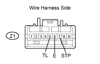 |
Disconnect the Z1 connector.
Connect the voltmeter's positive (+) lead to terminal Z1-7 and the negative (-) lead to terminal Z1-6.
Measure the voltage of the connector.
| Tester Connection | Condition | Specified Condition |
| Z1-7 (STP) - Z1-6 (E) | Brake pedal released | Below 1 V |
| Z1-7 (STP) - Z1-6 (E) | Brake pedal depressed | 10 to 14 V |
Connect the voltmeter's positive (+) lead to terminal Z1-5 and the negative (-) lead to terminal Z1-6.
Measure the voltage of the connector.
| Tester Connection | Condition | Specified Condition |
| Z1-5 (TL) - Z1-6 (E) | Dimmer switch OFF | Below 1 V |
| Z1-5 (TL) - Z1-6 (E) | Dimmer switch ON | 10 to 14 V |
| 2. CHECK REAR COMBINATION LIGHT ASSEMBLY RH |
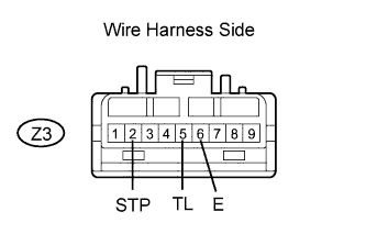 |
Disconnect the Z3 connector.
Connect the voltmeter's positive (+) lead to terminal Z3-2 and the negative (-) lead to terminal Z3-6.
Measure the voltage of the connector.
| Tester Connection | Condition | Specified Condition |
| Z3-2 (STP) - Z3-6 (E) | Brake pedal released | Below 1 V |
| Z3-2 (STP) - Z3-6 (E) | Brake pedal depressed | 10 to 14 V |
Connect the voltmeter's positive (+) lead to terminal Z3-5 and the negative (-) lead to terminal Z3-6.
Measure the voltage of the connector.
| Tester Connection | Condition | Specified Condition |
| Z3-5 (TL) - Z3-6 (E) | Dimmer switch OFF | Below 1 V |
| Z3-5 (TL) - Z3-6 (E) | Dimmer switch ON | 10 to 14 V |
| 3. CHECK REAR LIGHT ASSEMBLY LH |
 |
Disconnect the a2 connector.
Connect the voltmeter's positive (+) lead to terminal a2-2 and the negative (-) lead to terminal a2-4.
Measure the voltage of the connector.
| Tester Connection | Condition | Specified Condition |
| a2-2 (B) - a2-4 (E) | Dimmer switch ON | 10 to 14 V |
| a2-2 (B) - a2-4 (E) | Dimmer switch OFF | Below 1 V |
| 4. CHECK REAR LIGHT ASSEMBLY RH |
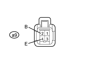 |
Disconnect the a9 connector.
Connect the voltmeter's positive (+) lead to terminal a9-2 and the negative (-) lead to terminal a9-4.
Measure the voltage of the connector.
| Tester Connection | Condition | Specified Condition |
| a9-2 (B) - a9-4 (E) | Dimmer switch ON | 10 to 14 V |
| a9-2 (B) - a9-4 (E) | Dimmer switch OFF | Below 1 V |
