Symbols (Terminal No.)
| Wiring Color
| Terminal Description
| Condition
| Specified Condition
|
B (L54-1) - GND (L54-20)
| S-B - BR
| Battery
| Always
| 10 to 14 V
|
ILL+ (L54-2) - GND (L54-20)
| G - BR
| Illumination signal
| Engine switch on (IG)
Light control switch OFF
| Below 1 V
|
Engine switch on (IG)
Light control switch TAIL or ON
| 10 to 14 V
|
MUTE (L54-7) - GND (L54-20)
| S-B - BR
| Mute signal
| Audio system is playing
| Above 3.5 V
|
Changing mode
| Below 1 V
|
MUTE (L53-6) - GND (L54-20)
| P - BR
| Mute signal
| Audio system is playing
| Above 3.5 V
|
Changing mode
| Below 1 V
|
R+ (L54-8) - GND (L54-20)
| R - BR
| Sound signal (Right)
| Audio system is playing
| -
|
L+ (L54-9) - GND (L54-20)
| B - BR
| Sound signal (Left)
| Audio system is playing
| -
|
R- (L54-18) - GND (L54-20)
| G - BR
| Sound signal (Right)
| Audio system is playing
| -
|
L- (L54-19) - GND (L54-20)
| W - BR
| Sound signal (Left)
| Audio system is playing
| -
|
GND (L54-20) - Body ground
| BR - Body ground
| Ground
| Always
| Below 1 Ω
|
SGND (L54-10) - Body ground
| Shielded - Body ground
| Ground
| Always
| Below 1 Ω
|
ACC (L54-11) - GND (L54-20)
| GR - BR
| Accessory (ON)
| Engine switch off
| Below 1 V
|
Engine switch on (ACC)
| 10 to 14 V
|
ILL- (L54-12) - GND (L54-10)
| W - BR
| Illumination signal
| Engine switch off
| Below 1 V
|
Engine switch on (IG)
| Pulse generation
|
TX+ (L56-9) - GND (L54-20)
| L - BR
| AVC-LAN communication signal
| Engine switch on (ACC)
| 2 to 3 V
|
TX- (L56-10) - GND (L54-20)
| LG - BR
| AVC-LAN communication signal
| Engine switch on (ACC)
| 2 to 3 V
|
TXM+ (L53-9) - GND (L54-20))
| Y - BR
| AVC-LAN communication signal
| Engine switch on (ACC)
| 2 to 3 V
|
TXM- (L53-10) - GND (L54-20)
| B - BR
| AVC-LAN communication signal
| Engine switch on (ACC)
| 2 to 3 V
|
ATX+ (L54-5) - GND (L54-20)
| L - BR
| AVC-LAN communication signal
| Engine switch on (ACC)
| 2 to 3 V
|
ATX- (L54-15) - GND (L54-20)
| LG - BR
| AVC-LAN communication signal
| Engine switch on (ACC)
| 2 to 3 V
|
ANT (L54 - 13)
| O - BR
| Antenna signal
| Audio system is playing
| -
|
SWG (L56-6) - GND (L54-20)
| LG - BR
| Steering pad switch signal
| Audio system is playing
| -
|
SW1 (L56-7) - GND (L54-20)
| Y - BR
| Steering pad switch signal
| Audio system is playing
| -
|
SW2 (L56-8) - GND (L54-20)
| O - BR
| Steering pad switch signal
| Audio system is playing
| -
|
Symbols (Terminal No.)
| Wiring Color
| Terminal Description
| Condition
| Specified Condition
|
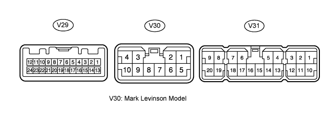
WFL+ *1 (V30-3) - GND (V31-16)
| W - W-B
| Sound signal (Front left)
| Audio system is playing
| -
|
WFR+ *1 (V30-4) - GND (V31-16)
| G - W-B
| Sound signal (Front right)
| Audio system is playing
| -
|
WFL- *1 (V30-9) - GND (V31-16)
| R - W-B
| Sound signal (Front left)
| Audio system is playing
| -
|
WFR- *1 (V30-10) - GND (V31-16)
| W - W-B
| Sound signal (Front right)
| Audio system is playing
| -
|
MUTE (V29-1) - GND (V31-16)
| O - W-B
| Mute signal from radio receiver
| Audio system is sounding
| Above 3.5 V
|
Changing mode
| Below 3.5 V
|
L- (V29-2) - GND (V31 -16)
| W - W-B
| Sound signal from radio receiver (Left)
| Audio system is playing
| -
|
L+ (V29-3) - GND (V31-16)
| B - W-B
| Sound signal from radio receiver (Left)
| Audio system is playing
| -
|
R- (V29-4) - GND (V31-16)
| G - W-B
| Sound signal from radio receiver (Right)
| Audio system is playing
| -
|
R+ (V29-5) - GND (V31-16)
| B - W-B
| Sound signal from radio receiver (Right)
| Audio system is playing
| -
|
TX- (V29-7) - GND (V31-16)
| L - W-B
| AVC-LAN communication signal
| Engine switch on (ACC)
| 2 to 3 V
|
TX+ (V29-8) - GND (V31-16)
| LG - W-B
| AVC-LAN communication signal
| Engine switch on (ACC)
| 2 to 3 V
|
ACC (V29-12) - GND (V31-16)
| GR - W-B
| Accessory (ON)
| Engine switch off
| Below 1 V
|
Engine switch on (ACC)
| 10 to 14 V
|
SPD (V29-11) - GND (V31-16)
| V - W-B
| Speed signal from combination meter
| Vehicle is being driven
| Pulse generation
|
TXD- *1, RTX- *2 (V29-19) - GND (V31-16)
| R - W-B
| AVC-LAN communication signal
| Engine switch on (ACC)
| 2 to 3 V
|
TXD+ *1, RTX+ *2 (V29-20) - GND (V31-16)
| G - W-B
| AVC-LAN communication signal
| Engine switch on (ACC)
| 2 to 3 V
|
TMUT (V29-24) - GND (V31-16)
| LG - W-B
| Mute signal from radio receiver
| Audio system is sounding
| Above 3.5 V
|
Changing mode
| Below 3.5 V
|
+B2 *1 (V31-10), +B *2 (V31-1) - GND (V31-16)
| SB - W-B
| Battery
| Always
| 10 to 14 V
|
RL+ (V31-6) - GND (V31-16)
| B - W-B
| Sound signal (Rear left)
| Audio system is playing
| -
|
RR+ (V31-7) - GND (V31-16)
| R - W-B
| Sound signal (Rear right)
| Audio system is playing
| -
|
FL+ (V31-8) - GND (V31-16)
| P - W-B
| Sound signal (Front left)
| Audio system is playing
| -
|
FR- (V31-20) - GND (V31-16)
| L - W-B
| Sound signal (Front right)
| Audio system is playing
| -
|
RL- (V31-17) - GND (V31-16)
| Y - W-B
| Sound signal (Rear left)
| Audio system is playing
| -
|
RR- (V31-18) - GND (V31-16)
| W - W-B
| Sound signal (Rear right)
| Audio system is playing
| -
|
FL- (V31-19) - GND (V31-16)
| V - W-B
| Sound signal (Front left)
| Audio system is playing
| -
|
FR+ (V31-9) - GND (V31-16)
| LG - W-B
| Sound signal (Front right)
| Audio system is playing
| -
|
GND (V31-16) - Body ground
| W-B - Body ground
| Ground
| Always
| Below 1 Ω
|
GND2 (V31-15) - Body ground
| W-B - Body ground
| Ground
| Always
| Below 1 Ω
|
SL+ *1 (V30-1) - GND (V31-16)
| LG - W-B
| Sound signal (Rear LH)
| Audio system is playing
| -
|
SL- *1 (V30-5) - GND (V31-16)
| L - W-B
| Sound signal (Rear LH)
| Audio system is playing
| -
|
SR+ *1 (V30-2) - GND (V31-16)
| B - W-B
| Sound signal (Rear RH)
| Audio system is playing
| -
|
SR- *1 (V30-6) - GND (V31-16)
| Y - W-B
| Sound signal (Rear RH)
| Audio system is playing
| -
|
WF1+ (V31-5) - GND
| P - W-B
| Sound signal (Woofer)
| Audio system is playing
| -
|
WF1- (V31-14) - GND
| V - W-B
| Sound signal (Woofer)
| Audio system is playing
| -
|
WF2+ (V31-4) - GND
| L - W-B
| Sound signal (Woofer)
| Audio system is playing
| -
|
WF2- (V31-13) - GND
| LG - W-B
| Sound signal (Woofer)
| Audio system is playing
| -
|
CTR+ (V31-3) - GND
| Y - W-B
| Sound signal (Center)
| Audio system is playing
| -
|
CTR- (V31-12) - GND
| B - W-B
| Sound signal (Center)
| Audio system is playing
| -
|
INT+ (V29-23) - GND
| Y - W-B
| AVC-LAN communication signal
| Engine switch on (ACC)
| 2 to 3 V
|
INT- (V29-22) - GND
| BR - W-B
| AVC-LAN communication signal
| Engine switch on (ACC)
| 2 to 3 V
|