AUDIO AND VISUAL SYSTEM > Radio Receiver Power Source Circuit |
| 1.CHECK RADIO RECEIVER (+B, ACC, GND) |
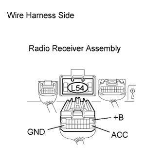 |
Disconnect the L54 radio receiver assembly connector.
Measure the resistance of the wire harness side connector.
| Tester Connection | Condition | Specified Condition |
| L54-20 (GND) - Body ground | Always | Below 1 Ω |
Measure the voltage according to the value(s) in the table below.
| Tester Connection | Condition | Specified Condition |
| L54-1 (+B) - L54-20 (GND) | Always | 10 to 14 V |
| L54-11 (ACC) - L54-20 (GND) | Engine switch on (ACC) | 10 to 14 V |
|
| ||||
| OK | ||
| ||
