AUDIO AND VISUAL SYSTEM > Steering Pad Switch Circuit |
| 1.CHECK RADIO RECEIVER ASSEMBLY |
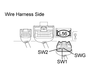 |
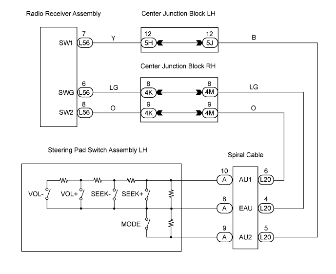
Disconnect the L56 receiver connector.
Measure the resistance of the wire harness side connector.
| Tester Connection | Condition | Specified Condition |
| L56-7 (SW1) - L56-6 (SWG) | No switch is pushed | Approx. 100 kΩ |
| L56-7 (SW1) - L56-6 (SWG) | SEEK+ switch: pushed | Approx. 0 Ω |
| L56-7 (SW1) - L56-6 (SWG) | SEEK- switch: pushed | Approx. 0.3 kΩ |
| L56-7 (SW1) - L56-6 (SWG) | VOL+ switch: pushed | Approx. 1 kΩ |
| L56-7 (SW1) - L56-6 (SWG) | VOL- switch: pushed | Approx. 3.2 kΩ |
| L56-8 (SW2) - L56-6 (SWG) | No switch is pushed | Approx. 100 kΩ |
| L56-8 (SW2) - L56-6 (SWG) | MODE switch: pushed | Approx. 0 Ω |
|
| ||||
| NG | |
| 2.INSPECT STEERING PAD SWITCH ASSEMBLY |
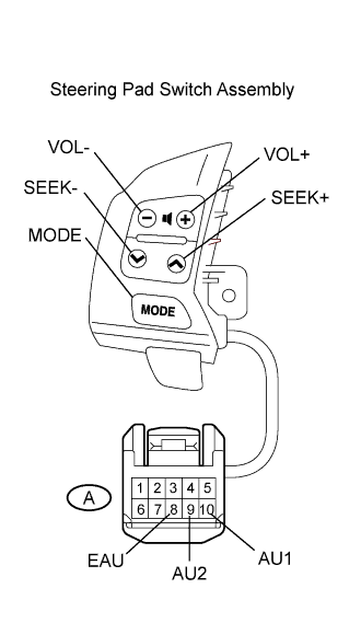 |
Remove the steering pad switch.
Measure the resistance of the connector.
| Tester Connection | Condition | Specified Condition |
| A-10 (AU1) - A-8 (EAU) | No switch is pushed | Approx. 100 kΩ |
| A-10 (AU1) - A-8 (EAU) | SEEK+ switch: pushed | Approx. 0 kΩ |
| A-10 (AU1) - A-8 (EAU) | SEEK- switch: pushed | Approx. 0.3 kΩ |
| A-10 (AU1) - A-8 (EAU) | VOL+ switch: pushed | Approx. 1 kΩ |
| A-10 (AU1) - A-8 (EAU) | VOL- switch: pushed | Approx. 3.2 kΩ |
| A-9 (AU2) - A-8 (EAU) | No switch is pushed | Approx. 100 kΩ |
| A-9 (AU2) - A-8 (EAU) | MODE switch: pushed | Approx. 0 kΩ |
|
| ||||
| OK | |
| 3.INSPECT SPIRAL CABLE |
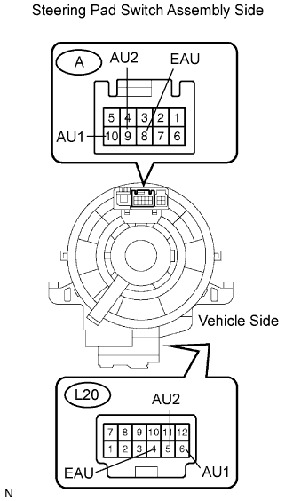 |
Disconnect the A steering pad switch and L20 spiral cable connectors.
Measure the resistance of the connectors.
| Tester Connection | Specified Condition |
| L20-4 (EAU) - A-8 (EAU) | Below 1 Ω |
| L20-6 (AU1) - A-10 (AU1) | Below 1 Ω |
| L20-5 (AU2) - A-9 (AU2) | Below 1 Ω |
|
| ||||
| OK | ||
| ||
