REAR PROPELLER SHAFT ASSEMBLY (for 3GR-FSE) > INSTALLATION |
| 1. INSTALL REAR PROPELLER SHAFT ASSEMBLY |
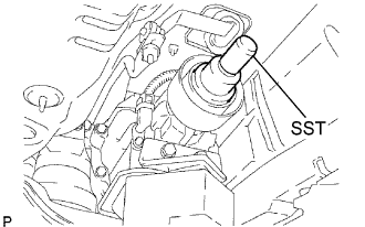 |
Remove the SST from the transmission.
Insert the yoke of the intermediate shaft into the transmission.
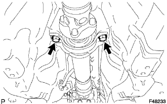 |
Install the 2 center support bearing washers and center support bearing, and temporarily tighten the 2 bolts.
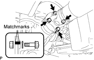 |
Align the matchmarks on the propeller shaft flange and differential companion flange, and connect the shaft with the 4 bolts, washers and nuts.
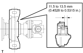 |
Adjust the dimension between the edge surface of the center support bearing and the edge surface of the cushion to 11.5 to 13.5 mm (0.4528 to 0.5315 in.) respectively as shown in illustration.
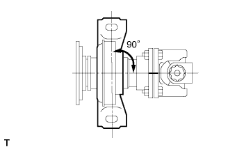 |
Check that the center line of the bracket is at right angles to the shaft axial direction.
|
Tighten the 2 bolts.
| 2. INSPECT AND ADJUST NO. 2 AND NO. 3 JOINT ANGLE |
Stabilize the propeller shaft and differential.
Turn the propeller shaft several times by hand to stabilize the center support bearing.
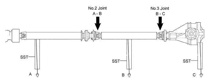
Check the No.2 and No.3 joint angles.
Using SST, measure the installation angle of the intermediate shaft and propeller shaft.
Using SST, measure the installation angle of the differential.
Calculate the No.2 joint angle.
Calculate the No.3 joint angle.
Adjust the No.2 joint angle .
Select the center support bearing washers for adjustment.
| Thickness mm (in.) |
| 2 (0.078) |
| 4.5 (0.1772) |
| 6.5 (0.2559) |
| 9.0 (0.3543) |
| 11 (0.4331) |
| 13.5 (0.5315) |
| 3. INSTALL FRONT FLOOR HEAT INSULATOR NO.1 |
Install the heat insulator No.1 with the 4 nuts and grommet.
| 4. INSTALL EXHAUST PIPE ASSEMBLY FRONT |
| 5. CHECK FOR EXHAUST GAS LEAKS |
