REAR PROPELLER SHAFT ASSEMBLY (for 3GR-FE) > DISASSEMBLY |
| 1. REMOVE PROPELLER SHAFT ASSEMBLY |
 |
Put matchmarks on both flanges.
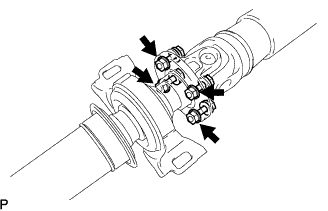 |
Remove the 4 nuts, bolts, washers and propeller shaft assembly.
| 2. REMOVE CENTER SUPPORT BEARING ASSEMBLY NO.1 |
Hold the intermediate shaft assembly in a vise between aluminium plates.
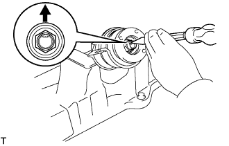 |
Using a chisel and a hammer, release the staked part of the nut.
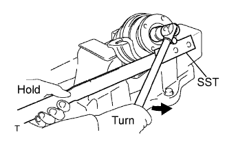 |
Using SST to hold the universal joint flange, remove the nut and intermediate shaft washer.
 |
Put matchmarks on the intermediate shaft assembly and universal joint flange.
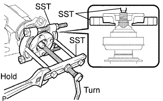 |
Using SST, remove the universal joint flange from the intermediate shaft assembly.
Remove the center support bearing assembly No.1 and 2 center support bearing washers from the intermediate shaft assembly.
Hold the intermediate shaft assembly in a vise between aluminium plates.
 |
Using a screwdriver and a hammer, remove the sliding shaft dust cover.
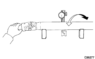
| 3. INSPECT PROPELLER SHAFT ASSEMBLY |
 |
Using a dial indicator, inspect the runout of the propeller shaft.
| 4. INSPECT INTERMEDIATE SHAFT |
 |
Using a dial indicator, inspect the runout of the intermediate shaft.
| 5. INSPECT SPIDER BEARING |
 |
Check that the spider bearing rotates smoothly.
Check that there is no play in the spider bearing.
| 6. INSPECT CENTER SUPPORT BEARING ASSEMBLY NO.1 |
 |
Turn the center support bearing by hand in the rotating direction. Check the center support bearing turns smoothly.
Check that the seals are not cracked or damaged.
