REAR AXLE HUB > REMOVAL |
| 1. REMOVE REAR WHEEL |
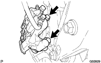
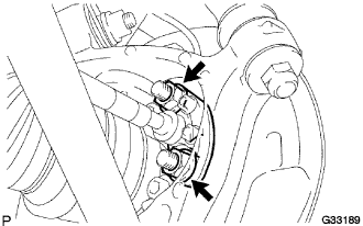
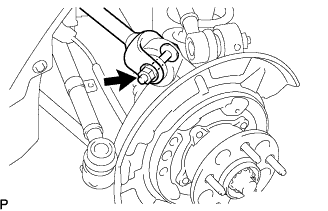
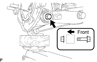
| 2. SEPARATE REAR STABILIZER LINK ASSEMBLY |
 |
Remove the bolt and nut, and separate the stabilizer link assembly and load sensing valve sensor bracket.
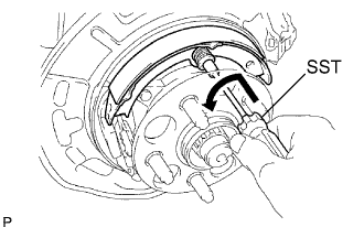
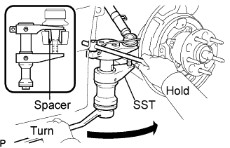
| 3. REMOVE REAR AXLE SHAFT NUT |
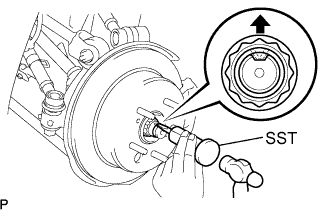 |
Using SST and a hammer, release the staked part of the axle shaft nut.
While applying the brakes, remove the rear axle shaft nut.
| 4. SEPARATE REAR DISC BRAKE CALIPER ASSEMBLY |
 |
Remove the 2 bolts, and disconnect the rear disc brake caliper assembly.
Remove the caliper plates No.1 from the brake caliper.
| 5. REMOVE REAR DISC |
| 6. SEPARATE SPEED SENSOR REAR |
 |
Remove the 2 bolts, and separate the speed sensor from the axle carrier.
| 7. REMOVE PARKING BRAKE SHOE RETURN SPRING NO.2 |
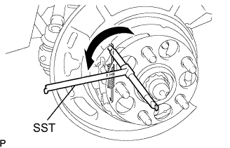 |
Using SST, remove the parking brake shoe return No.2 spring.
| 8. REMOVE PARKING BRAKE SHOE RETURN SPRING NO.1 |
 |
Using SST, remove the parking brake shoe return No.1 spring.
| 9. REMOVE PARKING BRAKE SHOE ADJUSTING SCREW SET |
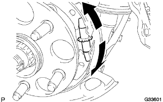 |
Slide the parking brake shoe, and remove the parking brake shoe adjusting screw set.
| 10. REMOVE PARKING BRAKE SHOE ASSEMBLY NO.1 |
 |
Using SST, remove the shoe hold down spring No.1 cup, compression No.1 spring and shoe hold down spring No.1 pin.
Remove the parking brake No.1 shoe assembly.
| 11. REMOVE PARKING BRAKE SHOE ASSEMBLY NO.2 |
 |
Using SST, remove the shoe hold down spring No.1 cup, compression No.1 spring and shoe hold down spring No.1 pin.
Remove the parking brake No.2 shoe assembly.
| 12. INSTALL PARKING BRAKE SHOE LEVER |
| 13. REMOVE PARKING BRAKE ANCHOR BLOCK |
 |
Remove the 2 nuts and the parking brake anchor block sub-assembly from the rear axle carrier sub-assembly.
| 14. SEPARATE UPPER CONTROL ARM ASSEMBLY REAR NO.2 |
Remove the nut from the upper control arm assembly rear No.2.
 |
Using SST, separate the upper control arm assembly rear No.2 from the rear axle carrier sub-assembly.
| 15. SEPARATE UPPER CONTROL ARM ASSEMBLY REAR NO.1 |
Jack up the rear axle assembly so that the bolt on the upper control arm assembly rear No.1 can be removed.
 |
Remove the bolt, washer and nut, and separate the upper control arm assembly rear No.1 from the rear axle carrier sub-assembly.
| 16. SEPARATE REAR SUSPENSION ARM ASSEMBLY NO.1 |
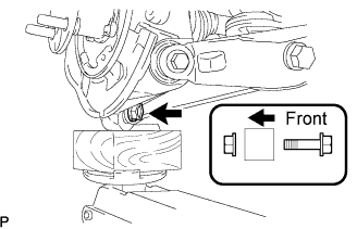 |
Remove the bolt and nut, and separate the rear suspension arm assembly No.1 from the rear axle carrier sub-assembly.
| 17. SEPARATE REAR SUSPENSION ARM ASSEMBLY NO.2 |
 |
Remove the bolt and nut, and separate the rear suspension arm assembly No.2 from the rear axle carrier sub-assembly.
| 18. SEPARATE TOE CONTROL LINK SUB-ASSEMBLY |
Remove the nut from the toe control link sub-assembly.
 |
Using SST, separate the toe control link sub-assembly from the rear axle carrier sub-assembly.
| 19. REMOVE REAR AXLE ASSEMBLY |
Using a plastic hammer, separate the drive shaft from the rear axle carrier sub-assembly.
Remove the rear axle assembly.
| 20. REMOVE REAR WHEEL BEARING DUST DEFLECTOR NO.2 |
 |
Using a screwdriver, remove the bearing dust deflector No.2 from the rear axle carrier sub-assembly.
| 21. REMOVE REAR AXLE HUB AND BEARING ASSEMBLY |
Hold the axle hub and bearing assembly in a vise between aluminium plates.
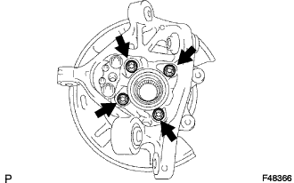 |
Remove the 4 bolts and axle hub and bearing assembly from the rear axle carrier sub-assembly.
