REAR DIFFERENTIAL CARRIER ASSEMBLY (for 3GR-FE) > DISASSEMBLY |
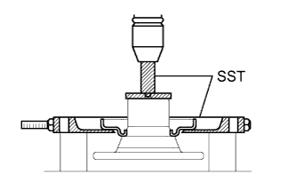
| 1. REMOVE NO.1 REAR DIFFERENTIAL MOUNT CUSHION |
 |
Using SST, remove the No.1 rear differential mount cushion.
| 2. REMOVE NO.2 REAR DIFFERENTIAL MOUNT CUSHION |
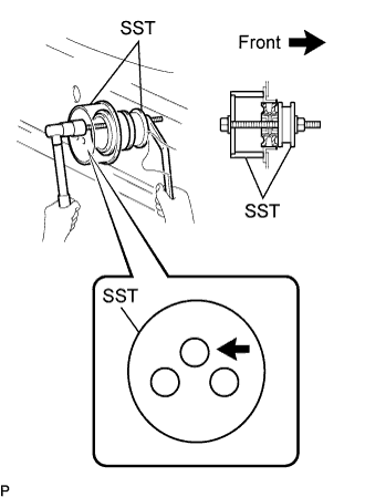 |
Using SST, remove the No.2 rear differential mount cushion.
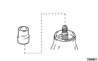
| 3. REMOVE REAR DIFFERENTIAL BREATHER PLUG |
 |
Remove the breather plug from the differential carrier cover.
| 4. REMOVE REAR DIFFERENTIAL CARRIER COVER |
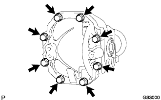 |
Remove the 8 bolts from the differential carrier cover.
 |
Using a brass bar and a hammer, remove the differential carrier cover from the differential carrier.
| 5. REMOVE REAR DIFFERENTIAL BREATHER PLUG OIL DEFLECTOR |
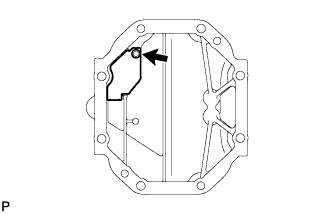 |
Remove the bolt and oil deflector from the differential carrier cover.
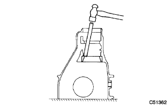
| 6. FIX REAR DIFFERENTIAL CARRIER |
 |
Set the differential carrier to an overhaul stand, etc., as shown in the illustration.
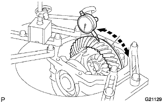
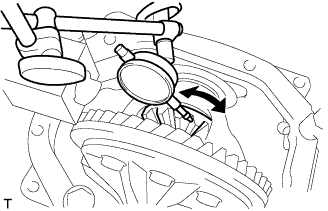
| 7. INSPECT RUNOUT OF DIFFERENTIAL RING GEAR |
 |
Set the dial indicator perpendicular to the end of the ring gear face.
Rotate the ring gear and measure the runout.
| 8. INSPECT DIFFERENTIAL RING GEAR BACKLASH |
 |
While holding the rear drive pinion companion flange, rotate the ring gear and measure the backlash.
| 9. INSPECT REAR DIFFERENTIAL SIDE GEAR BACKLASH |
 |
Using a dial indicator, check the backlash of the side gear while holding 1 pinion gear toward the differential case.
| 10. INSPECT RUNOUT OF REAR DRIVE PINION COMPANION FLANGE |
 |
Using a dial indicator, measure the runout of the companion flange vertically and horizontally.
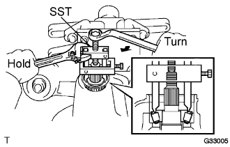
| 11. INSPECT TOTAL PRELOAD |
 |
Using a torque wrench, measure the preload with the teeth of the drive pinion and ring gear in contact.
| 12. REMOVE REAR DIFFERENTIAL SIDE GEAR SHAFT OIL SEAL |
 |
Using SST, remove the 2 oil seals.
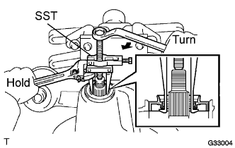
| 13. REMOVE REAR DRIVE PINION NUT |
 |
Using SST and a hammer, unstake the staked part of the drive pinion nut.
 |
Using SST to hold the flange, remove the drive pinion nut.
| 14. REMOVE REAR DRIVE PINION COMPANION FLANGE |
 |
Using SST, remove the companion flange.
| 15. REMOVE REAR DIFFERENTIAL DUST DEFLECTOR |
 |
Using SST and a press, remove the dust deflector.
| 16. REMOVE REAR DIFFERENTIAL CARRIER OIL SEAL |
 |
Using SST, remove the oil seal from the differential carrier.
| 17. REMOVE REAR DIFFERENTIAL DRIVE PINION OIL SLINGER |
 |
Remove the drive pinion oil slinger.
| 18. REMOVE REAR DRIVE PINION FRONT TAPERED ROLLER BEARING |
 |
Using SST, remove the inner race of the rear drive pinion front tapered roller bearing from the drive pinion.
| 19. REMOVE REAR DIFFERENTIAL DRIVE PINION BEARING SPACER |
 |
Remove the drive pinion bearing spacer.
| 20. REMOVE REAR DIFFERENTIAL CASE |
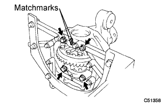 |
Put matchmarks on either set of the bearing cap and differential carrier.
Remove the 4 bolts and 2 bearing caps.
 |
Using SST and a hammer, remove the 2 side gear shaft plate washers.
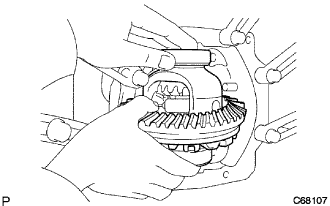 |
Remove the differential case assembly and the case bearing outer races LH and RH from the differential carrier.
| 21. REMOVE DIFFERENTIAL DRIVE PINION |
Remove the drive pinion from the differential carrier.
| 22. REMOVE REAR DRIVE PINION REAR TAPERED ROLLER BEARING |
 |
Using SST and a press, remove the inner race of the rear drive pinion rear tapered roller bearing from the drive pinion.
Remove the drive pinion plate washer from the drive pinion.
| 23. REMOVE REAR DRIVE PINION FRONT TAPERED ROLLER BEARING |
 |
Using a brass bar and a hammer, remove the outer race of the rear drive pinion front tapered roller bearing from the differential carrier.
| 24. REMOVE REAR DRIVE PINION REAR TAPERED ROLLER BEARING |
 |
Using a brass bar and a hammer, remove the outer race of the rear drive pinion rear tapered roller bearing from the differential carrier.
| 25. REMOVE DIFFERENTIAL RING GEAR |
 |
Hold the differential case in a vise between aluminum plates.
Put matchmarks on the ring gear and differential case.
Using a screwdriver and a hammer, unstake the 5 lock plates.
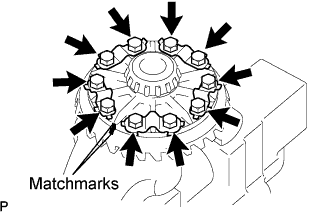 |
Remove the 10 ring gear set bolts and 5 lock plates.
Using a plastic hammer, tap on the ring gear to separate it from the differential case.
| 26. INSPECT RUNOUT OF DIFFERENTIAL CASE ASSEMBLY |
Install the case bearing outer races LH and RH to the case bearing inner races LH and RH respectively.
Install the differential case to the differential carrier.
Install the right and left (back side and teeth side) side gear shaft plate washers so that there is no looseness on the case bearings.
Install the right and left bearing caps with the 4 bolts.
 |
Using a dial indicator, measure the differential case runout.
Remove the right and left bearing caps, 2 side gear shaft plate washers and differential case.
| 27. REMOVE REAR DIFFERENTIAL CASE BEARING |
 |
Hold the differential case in a vise between aluminum plates.
Using SST, remove the case bearing inner race LH and RH from the differential case.
| 28. REMOVE REAR DIFFERENTIAL PINION SHAFT PIN |
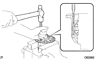 |
Using a pin punch (3 mm) and a hammer, remove the straight pin.
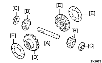 |
Remove the differential pinion shaft. [A]
Remove the 2 differential pinion gears. [B]
Remove the 2 differential pinion thrust washers. [C]
Remove the 2 side gears. [D]
Remove the 2 side gear thrust No.1 washers. [E]
| 29. INSPECT DIFFERENTIAL PINION AND SIDE GEAR |
Check that there is no damage to the differential pinion gear and side gear. If the differential pinion gear and/or side gear is damaged, replace them with new ones.
| 30. INSPECT REAR DIFFERENTIAL CASE |
Check that there is no damage to the differential case. If the differential case is damaged, replace it.
