REAR DIFFERENTIAL CARRIER ASSEMBLY (for 3GR-FE) > REASSEMBLY |
| 1. INSTALL REAR DIFFERENTIAL PINION SHAFT PIN |
 |
Install the 2 thrust No.1 washers to the 2 side gears.
Install the 2 side gears, 2 differential pinion gears, 2 differential pinion thrust washers and differential pinion shaft to the differential case.
 |
Hold the differential case in a vise between aluminum plates.
Measure the side gear backlash while holding 1 pinion gear toward the differential case.
| Thickness mm (in.) | Thickness mm (in.) |
| 1.48 to 1.52 (0.0583 to 0.0598) | 1.73 to 1.77 (0.0681 to 0.0697) |
| 1.53 to 1.57 (0.0602 to 0.0618) | 1.78 to 1.82 (0.0701 to 0.0717) |
| 1.58 to 1.62 (0.0622 to 0.0638) | 1.83 to 1.87 (0.0720 to 0.0736) |
| 1.63 to 1.67 (0.0642 to 0.0657) | 1.88 to 1.92 (0.0740 to 0.0756) |
| 1.68 to 1.72 (0.0661 to 0.0677) | - |
 |
Using a pin punch (3 mm) and a hammer, install the straight pin through the differential case and hole of the pinion shaft.
 |
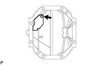
Using a chisel and a hammer, stake the outside of the differential case pin hole.
| 2. INSTALL DIFFERENTIAL RING GEAR |
 |
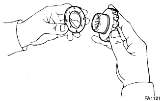
Clean the contact surfaces of differential case and ring gear.
Clean the differential ring gear set bolt hole.
Heat the ring gear to approx. 100°C (212°F) in boiling water.
Carefully take the ring gear out of the boiling water.
Hold the differential case in a vise between aluminum plates.
After the moisture on the ring gear has completely evaporated, quickly install the ring gear to the differential case.
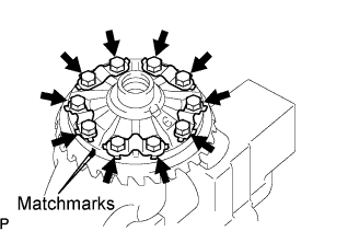 |
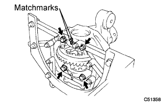
Align the matchmarks on the ring gear and differential case.
Temporarily install 5 new lock plates and 10 bolts.
After the ring gear cools down, tighten the 10 bolts uniformly.
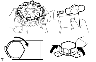 |
Using a chisel and a hammer, stake the 5 lock plates.
Stake one claw so that it is flush against the flat surface of the bolt.
Stake the other claw against the surface of the bolt head to act as a stopper if the bolt starts to loosen.
| 3. INSTALL REAR DIFFERENTIAL CASE BEARING |
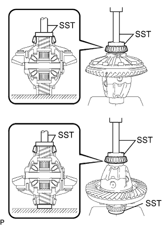 |
Using SST and a press, install the case bearing inner race LH and RH to the differential case.
| 4. INSPECT RUNOUT OF DIFFERENTIAL RING GEAR |
 |
Install the case bearing outer race LH and RH to the case bearing inner race LH and RH respectively.
Install the differential case to the differential carrier.
Install the right and left (back side and teeth side) side gear shaft plate washers so that there is no looseness on the case bearing.
Install the right and left bearing caps with the 4 bolts.
 |
Using a dial indicator, measure the runout of the ring gear.
Remove the right and left bearing caps, 2 side gear shaft plate washers and differential case.
| 5. INSTALL REAR DRIVE PINION REAR TAPERED ROLLER BEARING |
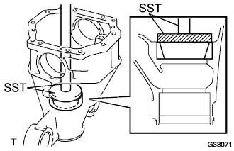 |
Using SST and a press, install the outer race of the rear drive pinion rear tapered roller bearing to the differential carrier.
| 6. INSTALL REAR DRIVE PINION FRONT TAPERED ROLLER BEARING |
 |
Using SST and a press, install the outer race of the rear drive pinion front tapered roller bearing to the differential carrier.
| 7. INSTALL REAR DRIVE PINION REAR TAPERED ROLLER BEARING |
 |
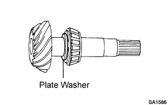
Install the drive pinion plate washer to the drive pinion.
Using SST and a press, install the inner race of the rear drive pinion rear tapered roller bearing to the drive pinion.
| 8. ADJUST DIFFERENTIAL DRIVE PINION PRELOAD |
 |
Install the drive pinion and the inner race of the rear drive pinion front tapered roller bearing to the differential carrier.
 |
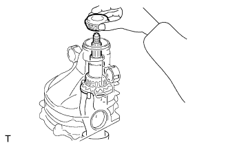
Install the drive pinion oil slinger to the drive pinion.
 |
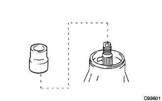
Using SST, install the companion flange.
Coat the threads of the drive pinion nut with hypoid gear oil LSD.
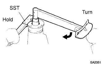 |
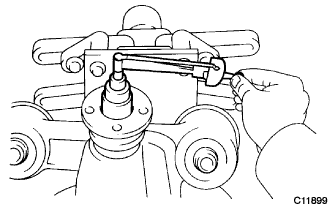
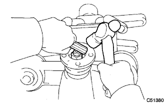
Using SST to hold the flange, tighten the drive pinion nut.
Turn the bearing clockwise and counterclockwise several times to stabilize it.
 |
Using a torque wrench, measure the preload.
| 9. INSTALL REAR DIFFERENTIAL CASE |
Install the case bearing outer races LH and RH to the case bearing inner races LH and RH respectively.
Install the differential case to the differential carrier.
| 10. INSPECT DIFFERENTIAL RING GEAR AND DIFFERENTIAL DRIVE PINION BACKLASH |
 |
Set the dial indicator perpendicular to the end of the ring gear face.
While holding the rear drive pinion companion flange, rotate the ring gear and measure the backlash.
| 11. ADJUST DIFFERENTIAL RING GEAR AND DIFFERENTIAL DRIVE PINION BACKLASH |
 |
Select a side gear shaft plate washer that will set ring gear backlash within the specified range, and install it to the ring gear back side.
| Thickness mm (in.) | Thickness mm (in.) | Thickness mm (in.) |
| 2.57 to 2.59 (0.1012 to 0.1020) | 2.89 to 2.91 (0.1138 to 0.1146) | 3.21 to 3.23 (0.1264 to 0.1271) |
| 2.59 to 2.61 (0.1020 to 0.1028) | 2.91 to 2.93 (0.1146 to 0.1154) | 3.23 to 3.25 (0.1271 to 0.1280) |
| 2.61 to 2.63 (0.1028 to 0.1035) | 2.93 to 2.95 (0.1154 to 0.1161) | 3.25 to 3.27 (0.1280 to 0.1287) |
| 2.63 to 2.65 (0.1035 to 0.1043) | 2.95 to 2.97 (0.1161 to 0.1169) | 3.27 to 3.29 (0.1287 to 0.1295) |
| 2.65 to 2.67 (0.1043 to 0.1051) | 2.97 to 2.99 (0.1169 to 0.1177) | 3.29 to 3.31 (0.1295 to 0.1303) |
| 2.67 to 2.69 (0.1051 to 0.1059) | 2.99 to 3.01 (0.1177 to 0.1185) | 3.31 to 3.33 (0.1303 to 0.1311) |
| 2.69 to 2.71 (0.1059 to 0.1067) | 3.01 to 3.03 (0.1185 to 0.1193) | 3.33 to 3.35 (0.1311 to 0.1319) |
| 2.71 to 2.73 (0.1067 to 0.1075) | 3.03 to 3.05 (0.1193 to 0.1201) | 3.35 to 3.37 (0.1319 to 0.1327) |
| 2.73 to 2.75 (0.1075 to 0.1083) | 3.05 to 3.07 (0.1201 to 0.1209) | 3.37 to 3.39 (0.1327 to 0.1335) |
| 2.75 to 2.77 (0.1083 to 0.1091) | 3.07 to 3.09 (0.1209 to 0.1217) | 3.39 to 3.41 (0.1335 to 0.1343) |
| 2.77 to 2.79 (0.1091 to 0.1098) | 3.09 to 3.11 (0.1217 to 0.1224) | 3.41 to 3.43 (0.1343 to 0.1350) |
| 2.79 to 2.81 (0.1098 to 0.1106) | 3.11 to 3.13 (0.1224 to 0.1232) | 3.43 to 3.45 (0.1350 to 0.1358) |
| 2.81 to 2.83 (0.1106 to 0.1114) | 3.13 to 3.15 (0.1232 to 0.1240) | 3.45 to 3.47 (0.1358 to 0.1366) |
| 2.83 to 2.85 (0.1114 to 0.1122) | 3.15 to 3.17 (0.1240 to 0.1248) | 3.47 to 3.49 (0.1366 to 0.1374) |
| 2.85 to 2.87 (0.1122 to 0.1130) | 3.17 to 3.19 (0.1248 to 0.1256) | - |
| 2.87 to 2.89 (0.1130 to 0.1138) | 3.19 to 3.21 (0.1256 to 0.1264) | - |
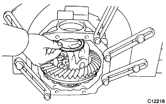
Make snug the differential case bearing and side gear shaft plate washer by tapping on the ring gear with a plastic hammer.
|
Set the dial indicator perpendicular to the end of the ring gear face.
While holding the rear drive pinion companion flange rear, rotate the ring gear and measure the backlash.
|
If the backlash is not within the specified range, select a side gear shaft plate washer that will set the ring gear backlash within the specified range and install it into the ring gear back side.
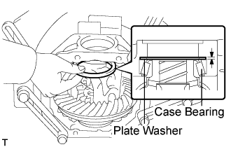 |
Select a thicker side gear shaft plate washer so that the clearance between the case bearing outer race end on the ring gear teeth side and the carrier becomes 0 or around 0.
Make the differential case bearing and side gear shaft plate washer snug by tapping on the ring gear with a plastic hammer.
|
Set the dial indicator perpendicular to the end of the ring gear face.
While holding the rear drive pinion companion flange rear, rotate the ring gear and measure the backlash.
| 12. ADJUST DIFFERENTIAL SIDE BEARING PRELOAD |
 |
After adjusting the backlash of the differential ring gear, remove the teeth side gear shaft plate washer.
Using a micrometer, measure the thickness of the removed side gear shaft plate washer.
Select a new side gear shaft plate washer which is 0.06 to 0.09 mm (0.0024 to 0.0035 in.) thicker than the removed one.
 |
Using SST and a plastic hammer, drive in the side gear shaft plate washer.
|
Align matchmarks on the bearing cap and differential carrier, and install the 2 bearing caps.
Tighten both bearing caps with the 4 bolts.
 |
Set the dial indicator to the end of the differential ring gear face.
While holding the rear drive pinion companion flange rear, rotate the differential ring gear and measure the backlash.
| 13. INSPECT TOTAL PRELOAD |
 |
Using a torque wrench, measure the preload with the teeth of the drive pinion and ring gear in contact.
| 14. INSPECT TOOTH CONTACT BETWEEN RING GEAR AND DRIVE PINION |
 |
Coat 3 or 4 teeth at 3 different positions on the ring gear with red lead primer.
Rotate the ring gear in both directions.
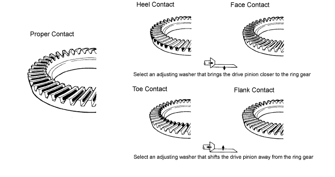
Inspect the tooth contact pattern.
 |
If the teeth are not contacting properly, use the following table to select a proper washer for correction.
| Thickness mm (in.) | Thickness mm (in.) | Thickness mm (in.) |
| 1.69 to 1.71 (0.0665 to 0.0673) | 1.93 to 1.95 (0.0760 to 0.0768) | 2.17 to 2.19 (0.0854 to 0.0862) |
| 1.72 to 1.74 (0.0677 to 0.0685) | 1.96 to 1.98 (0.0772 to 0.0780) | 2.20 to 2.22 (0.0866 to 0.0874) |
| 1.75 to 1.77 (0.0688 to 0.0697) | 1.99 to 2.01 (0.0783 to 0.0791) | 2.23 to 2.25 (0.0878 to 0.0886) |
| 1.78 to 1.80 (0.0701 to 0.0709) | 2.02 to 2.04 (0.0795 to 0.0803) | 2.26 to2.28 (0.0890 to 0.0898) |
| 1.81 to 1.83 (0.0713 to 0.0720) | 2.05 to 2.07 (0.0807 to 0.0815) | 2.29 to 2.31 (0.0902 to 0.0909) |
| 1.84 to 1.86 (0.0724 to 0.0732) | 2.08 to 2.10 (0.0819 to 0.0827) | 2.32 to 2.34 (0.0913 to 0.0921) |
| 1.87 to 1.89 (0.0736 to 0.0744) | 2.11 to 2.13 (0.0831 to 0.0839) | - |
| 1.90 to 1.92 (0.0748 to 0.0756) | 2.14 to 2.16 (0.0843 to 0.0850) | - |
| 15. REMOVE REAR DRIVE PINION NUT |
| 16. REMOVE REAR DRIVE PINION COMPANION FLANGE |
| 17. REMOVE REAR DIFFERENTIAL DRIVE PINION OIL SLINGER |
| 18. REMOVE REAR DRIVE PINION FRONT TAPERED ROLLER BEARING |
| 19. INSTALL REAR DIFFERENTIAL DRIVE PINION BEARING SPACER |
 |
Install a new drive pinion bearing spacer to the drive pinion.
| 20. INSTALL REAR DRIVE PINION FRONT TAPERED ROLLER BEARING |
|
Install the rear drive pinion front tapered roller bearing to the drive pinion.
| 21. INSTALL REAR DIFFERENTIAL DRIVE PINION OIL SLINGER |
|
Install the drive pinion oil slinger to the drive pinion.
| 22. INSTALL REAR DIFFERENTIAL CARRIER OIL SEAL |
 |
Using SST and a hammer, install a new oil seal.
Apply MP grease to the oil seal lip.
| 23. INSTALL REAR DIFFERENTIAL DUST DEFLECTOR |
 |
Using SST and a press, install a new dust deflector.
| 24. INSTALL REAR DRIVE PINION COMPANION FLANGE |
 |
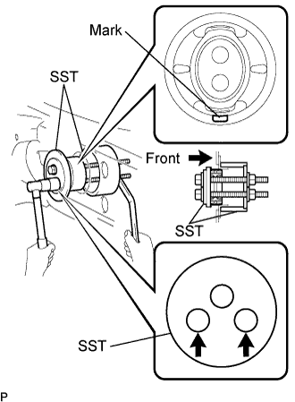
Using SST, install the companion flange to the drive pinion.
Coat the threads of a new drive pinion nut with hypoid gear oil LSD.
|
Using SST to hold the flange, tighten the drive pinion nut.
| 25. ADJUST DIFFERENTIAL DRIVE PINION PRELOAD |
Using a torque wrench, measure the preload of the drive pinion.
| 26. INSPECT TOTAL PRELOAD |
|
Using a torque wrench, measure the preload with the teeth of the drive pinion and ring gear in contact.
| 27. INSTALL REAR DRIVE PINION NUT |
 |
Using a chisel and hammer, stake the drive pinion nut.
| 28. INSTALL REAR DIFFERENTIAL SIDE GEAR SHAFT OIL SEAL |
 |
Using SST and a hammer, install 2 new oil seals.
Apply MP grease to the oil seal lip.
| 29. REMOVE REAR DIFFERENTIAL CARRIER |
 |
Remove the differential carrier from the overhaul stand, etc.
| 30. INSTALL REAR DIFFERENTIAL BREATHER PLUG OIL DEFLECTOR |
 |
Install the oil deflector and bolt to the carrier cover.
| 31. INSTALL REAR DIFFERENTIAL CARRIER COVER |
Clean any residual FIPG material on the contact surfaces using gasoline or alcohol.
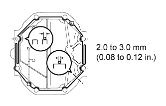 |
Apply FIPG to the carrier cover.
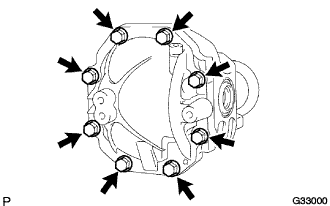 |
Install the carrier cover with the 8 bolts.
| 32. INSTALL REAR DIFFERENTIAL BREATHER PLUG |
 |
Install the breather plug to the carrier cover.
| 33. INSTALL REAR DIFFERENTIAL DRAIN PLUG |
Using a hexagon wrench (10 mm), install the differential drain plug with a new gasket.
| 34. INSTALL NO.1 REAR DIFFERENTIAL MOUNT CUSHION |
 |
Using SST, install a new No.1 rear differential mount cushion.
| 35. INSTALL NO.2 REAR DIFFERENTIAL MOUNT CUSHION |
 |
Using SST, install a new No.2 rear differential mount cushion.
