AUTOMATIC TRANSMISSION UNIT > DISASSEMBLY |
| 1. REMOVE TRANSAXLE CASE COVER UPPER |
Remove the 2 bolts and transaxle case cover upper.
| 2. REMOVE TRANSMISSION CONTROL SHAFT LEVER RH |
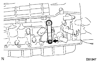 |
Remove the nut, spring washer and the transmission control shaft lever RH.
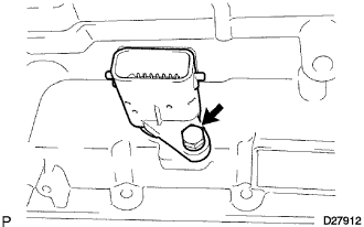
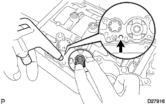
| 3. REMOVE PARK/NEUTRAL POSITION SWITCH ASSEMBLY |
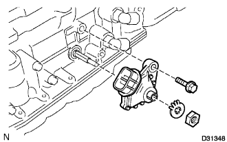 |
Using a screwdriver, unstake the lock washer.
Remove the nut and lock washer.
Remove the bolt and park/neutral position switch.
| 4. REMOVE OIL COOLER TUBE UNION |
 |
Remove the 2 oil cooler tube unions.
Remove the O-rings from the oil cooler tube unions.
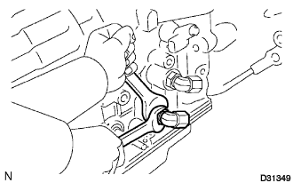
| 5. REMOVE TRANSMISSION REVOLUTION SENSOR |
 |
Remove the 2 bolts and the 2 transmission revolution sensors.
Remove the O-rings from each sensor.
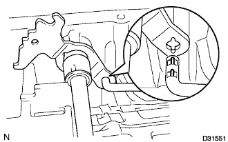
| 6. REMOVE AUTOMATIC TRANSMISSION BREATHER TUBE |
 |
Remove the 2 bolts.
Remove the breather tube.
| 7. REMOVE AUTOMATIC TRANSMISSION HOUSING |
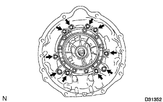 |
Remove the 10 bolts.
Remove the transmission housing.
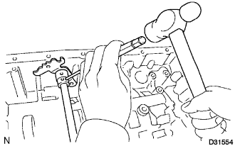
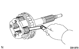
| 8. REMOVE AUTOMATIC TRANSMISSION FLANGE YOKE ASSEMBLY |
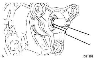 |
Using a hammer and chisel, loosen the staked part of the nut.
Remove the nut and flange yoke.
 |
Remove the oil seal from the flange yoke.
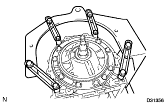
| 9. REMOVE EXTENSION (ATM) HOUSING SUB-ASSEMBLY |
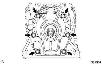 |
Remove the 6 bolts.
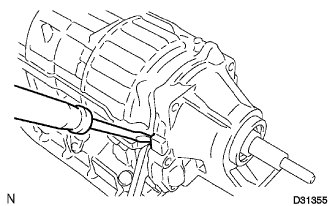 |
Use a screwdriver to remove the extension housing sub-assembly.
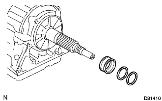
 |
Using a snap ring expander, remove the snap ring.
Remove the thrust needle roller bearing and the 2 bearing races.
| 10. REMOVE RR COVER SLEEVE |
 |
Remove the 2 washers and RR cover sleeve.
| 11. REMOVE TRANSMISSION CASE ADAPTOR RADIAL BALL BEARING |
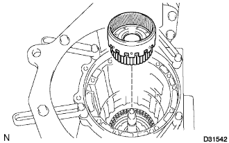
Remove the transmission case adaptor radial ball bearing from the extension housing sub-assembly.
| 12. REMOVE AUTOMATIC TRANSMISSION EXTENSION HOUSING OIL SEAL |
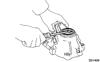 |
Using a screwdriver, remove the oil seal.
| 13. FIX AUTOMATIC TRANSMISSION CASE SUB-ASSEMBLY |
 |
Install the transmission case on the overhaul attachment.
| 14. REMOVE AUTOMATIC TRANSMISSION OIL PAN SUB-ASSEMBLY |
Remove the over flow plug and the gasket.
Remove the drain plug and the gasket.
Remove the 20 bolts, oil pan and gasket.
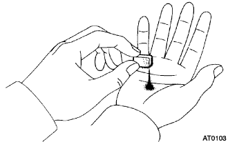 |
Examine particles in the pan.
Remove the magnets from the oil pan. Use the removed magnets to collect any steel chips. Look carefully at the chips and particles in the pan and on the magnet to anticipate the type of wear which might be found in the transmission.
Steel (magnetic): bearing, gear and plate wear
Brass (non-magnetic): bearing wear
| 15. REMOVE VALVE BODY OIL STRAINER ASSEMBLY |
 |
Turn over the transmission.
Remove the 4 bolts and valve body oil strainer assembly from the valve body.
Remove the O-ring from the valve body oil strainer assembly.
| 16. REMOVE TRANSMISSION WIRE |
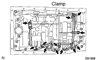 |
Remove the 3 bolts and disconnect the 3 clamps.
Disconnect the 9 connectors from the shift solenoid valves.
 |
Remove the bolt from the transmission case.
Pull the transmission wire out of the transmission case.
Remove the O-ring from the transmission wire.
| 17. REMOVE TRANSMISSION VALVE BODY ASSEMBLY |
 |
Remove the bolt, the detent spring cover and detent spring.
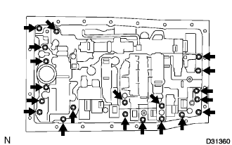 |
Remove the 20 bolts.
Remove the valve body assembly.
| 18. REMOVE TRANSAXLE CASE GASKET |
 |
Remove the 3 transaxle case gaskets.
| 19. REMOVE BRAKE DRUM GASKET |
 |
Remove the 3 brake drum gaskets.
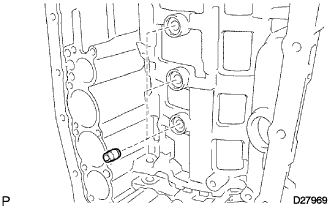
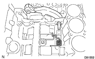
| 20. REMOVE CHECK BALL BODY |
 |
Remove the check ball body and the spring.
| 21. REMOVE C-2 ACCUMULATOR PISTON |
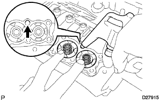 |
While blowing compressed air into the oil hole, remove the C-2 accumulator piston and the spring.
Remove the 2 O-rings from the piston.
| 22. REMOVE B-3 ACCUMULATOR PISTON |
While blowing compressed air into the oil hole, remove the B-3 accumulator piston and the spring.
Remove the 2 O-rings from the piston.
| 23. REMOVE C-3 ACCUMULATOR PISTON |
 |
While blowing compressed air into the oil hole, remove the C-3 accumulator piston and the 2 springs.
Remove the 2 O-rings from the piston.
| 24. REMOVE B-1 ACCUMULATOR VALVE |
 |
Remove the B-1 accumulator valve and the 2 springs.
| 25. REMOVE PARKING LOCK PAWL BRACKET |
 |
Remove the 3 bolts and the parking lock pawl bracket.
| 26. REMOVE PARKING LOCK ROD SUB-ASSEMBLY |
 |
Disconnect the parking lock rod from the manual valve lever.
| 27. REMOVE PARKING LOCK PAWL SHAFT |
 |
Pull out the parking lock pawl shaft from the front side, then remove the lock pawl and the spring.
Remove the E-ring from the shaft.
| 28. REMOVE MANUAL VALVE LEVER SUB-ASSEMBLY |
 |
Using a hammer and a screwdriver, cut off the spacer and remove it from the shaft.
 |
Using a pin punch and a hammer, drive out the spring pin.
Pull the manual valve lever shaft out through the case, and remove the manual valve lever.
| 29. REMOVE MANUAL VALVE LEVER SHAFT OIL SEAL |
 |
Using a screwdriver, remove the 2 oil seals.
| 30. REMOVE OIL PUMP ASSEMBLY |
 |
Remove the 10 bolts from the transmission case.
 |
Using a screwdriver with its tip wrapped with tape, pull out the oil pump.
 |
Remove the thrust bearing race No.1 from the oil pump.
Remove the O-ring from the oil pump.
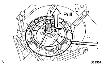
| 31. REMOVE CLUTCH DRUM AND INPUT SHAFT |
 |
Remove the clutch drum and input shaft from the transmission case.
 |
Remove the clutch drum thrust washer, 2 thrust needle roller bearings and bearing race.
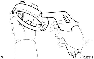
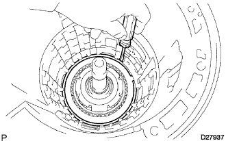
| 32. INSPECT 1 WAY NO.2 CLUTCH ASSEMBLY |
 |
Hold the reverse clutch hub and turn the 1 way No.2 clutch assembly .
Check that the 1 way No.2 clutch assembly turns freely clockwise and locks counterclockwise.
If there is a problem with the 1 way clutch, replace it.
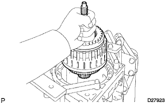
| 33. REMOVE 1 WAY NO.2 CLUTCH ASSEMBLY |
 |
Remove the 1 way No.2 clutch assembly and clutch drum thrust washer from the clutch drum and input shaft.
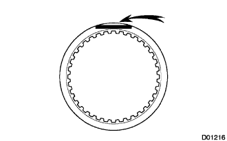
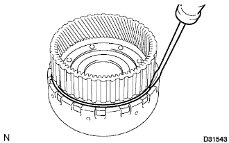
| 34. REMOVE BRAKE NO.3 SNAP RING |
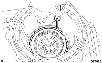 |
Using a screwdriver, remove the brake No.3 snap ring from the transmission case.
| 35. REMOVE 2ND BRAKE DISC SET |
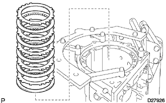 |
Remove the flange, cushion plate, 4 discs and 4 plates from the transmission case.
| 36. INSPECT 2ND BRAKE DISC SET |
 |
Check whether the sliding surfaces of the discs, the plates, or the flange are worn or burnt.
If necessary, replace them.
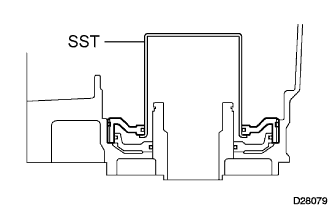
| 37. REMOVE 2ND BRAKE PISTON HOLE SNAP RING |
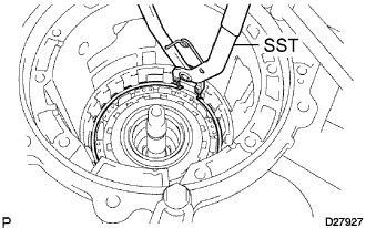 |
Using SST, remove the snap ring.
| 38. REMOVE 1 WAY CLUTCH ASSEMBLY |
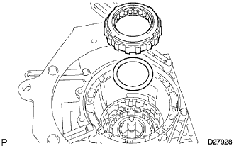 |
Remove the 1 way clutch assembly and the planetary carrier thrust washer No.1 from the transmission case.
| 39. REMOVE 2ND BRAKE CYLINDER |
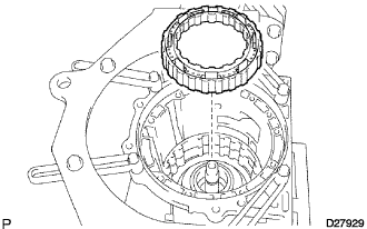 |
Remove the 2nd brake cylinder from the transmission case.
| 40. REMOVE 2ND BRAKE PISTON |
 |
Using SST and a press, remove the 2nd brake piston snap ring.
Remove the brake piston return spring sub-assembly No.3.
 |
Hold the 2nd brake piston and apply compressed air (392 kPa, 4.0 kgf/cm2, 57 psi) to the 2nd brake cylinder to remove the 2nd brake piston.
 |
Remove the 2 O-rings from the 2nd brake piston.
| 41. INSPECT BRAKE PISTON RETURN SPRING SUB-ASSEMBLY NO.3 |
 |
Using vernier calipers, measure the free length of the spring together with the spring seat.
| 42. REMOVE FRONT PLANETARY GEAR ASSEMBLY |
 |
Remove the front planetary gear assembly and the 1 way clutch inner race from the transmission case.
 |
Remove the thrust needle roller bearing, the thrust bearing race No.3 and the planetary carrier thrust washer No.2 from the transmission case.
| 43. INSPECT FRONT PLANETARY GEAR ASSEMBLY |
 |
Using a feeler gauge, measure the front planetary pinion gear thrust clearance.
 |
Using a dial indicator, measure the inside diameter of the front planetary gear bushing.
| 44. INSPECT 1 WAY CLUTCH ASSEMBLY |
 |
Install the 1 way clutch assembly to the 1 way clutch inner race.
Hold the 1 way clutch inner race and turn the 1 way clutch assembly.
Check that the 1 way clutch assembly turns freely counterclockwise and locks clockwise.
If there is a problem with the 1 way clutch, replace it.
Remove the 1 way clutch assembly from the 1 way clutch inner race.
| 45. REMOVE FRONT PLANETARY RING GEAR |
 |
Remove the front planetary ring gear from the transmission case.
| 46. REMOVE CENTER PLANETARY RING GEAR |
 |
Using a screwdriver, remove the snap ring.
 |
Remove the center planetary ring gear and the front planetary ring gear flange from the front planetary ring gear.
Remove the thrust needle roller bearing from the front planetary ring gear flange.
| 47. REMOVE BRAKE DISC NO.1 |
 |
Remove the flange, the 3 discs and the 3 plates from the transmission case.
| 48. INSPECT BRAKE DISC NO.1 |
|
Check whether the sliding surfaces of the discs, the plates, or the flange are worn or burnt.
If necessary, replace them.
| 49. REMOVE BRAKE PISTON RETURN SPRING SNAP RING |
 |
Using a screwdriver, remove the brake piston return spring snap ring from the transmission case.
| 50. REMOVE BRAKE PISTON RETURN SPRING SUB-ASSEMBLY |
 |
Remove the brake piston return spring and the brake piston No.1 with the brake cylinder No.1 from the transmission case.
| 51. INSPECT BRAKE PISTON RETURN SPRING SUB-ASSEMBLY |
 |
Using vernier calipers, measure the free length of the spring together with the spring seat.
| 52. REMOVE BRAKE PISTON NO.1 |
 |
Hold the brake cylinder No.1 and apply compressed air (392 kPa, 4 kgf/cm2, 57 psi) to the brake cylinder No.1 to remove the brake piston No.1.
Remove the 2 O-rings from the brake piston No.1.
| 53. REMOVE BRAKE DISC NO.2 |
 |
Using a screwdriver, remove the brake No.2 snap ring from the transmission case.
 |
Remove the 2 flanges, the brake piston return spring, the 4 discs and the 3 plates from the transmission case.
| 54. INSPECT BRAKE DISC NO.2 |
|
Check whether the sliding surfaces of the discs, the plates, and the flange are worn or burnt.
If necessary, replace them.
| 55. INSPECT BRAKE PISTON RETURN SPRING SUB-ASSEMBLY NO.2 |
 |
Using vernier calipers, measure the free length of the spring together with the spring seat.
| 56. REMOVE BRAKE PISTON NO.2 |
 |
Hold the brake piston No.2 and apply compressed air (392 kPa, 4 kgf/cm2, 57 psi) to the transmission case to remove the brake piston No.2 with the cylinder.
Remove the piston from the cylinder.
Remove the 2 O-rings from the brake piston No.2.
| 57. REMOVE CENTER PLANETARY GEAR ASSEMBLY |
 |
Remove the center planetary gear assembly, the planetary sun gear and the thrust bearing race No.4 from the transmission case.
| 58. INSPECT CENTER PLANETARY GEAR ASSEMBLY |
 |
Using a feeler gauge, measure the center planetary gear pinion thrust clearance.
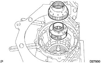
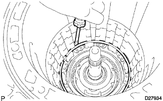
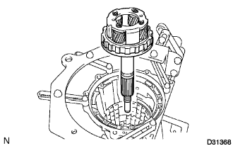
| 59. REMOVE INTERMEDIATE SHAFT |
 |
Using SST, remove the snap ring from the transmission case.
 |
Remove the intermediate shaft with the 1 way No.3 clutch assembly from the transmission case.
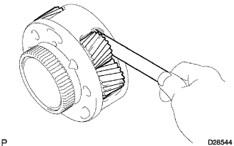
| 60. INSPECT 1 WAY NO.3 CLUTCH ASSEMBLY |
 |
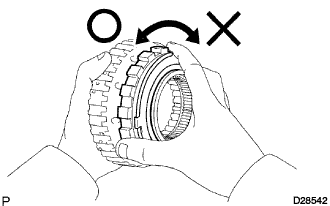
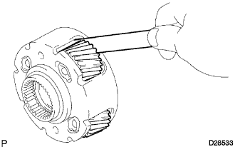
Hold the rear planetary ring gear flange sub-assembly and turn the 1 way clutch assembly.
Check that the 1 way clutch assembly turns freely counterclockwise and locks clockwise.
If there is a problem with the 1 way clutch, replace it.
| 61. REMOVE 1 WAY NO.3 CLUTCH ASSEMBLY |
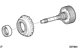 |
Remove the 1 way No.3 clutch assembly and the 1 way clutch inner race from the intermediate shaft.
| 62. REMOVE REAR PLANETARY RING GEAR FLANGE SUB-ASSEMBLY |
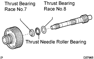 |
Remove the thrust bearing race No.8, the thrust needle roller bearing, the thrust bearing race No.7 and the planetary ring gear flange from the intermediate shaft.
| 63. INSPECT REAR PLANETARY RING GEAR FLANGE SUB-ASSEMBLY |
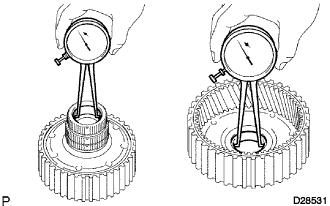 |
Using a dial indicator, measure the inside diameter of the rear planetary ring gear bushing.
| 64. INSPECT INTERMEDIATE SHAFT |
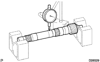 |
Using a dial indicator, check the intermediate shaft runout.
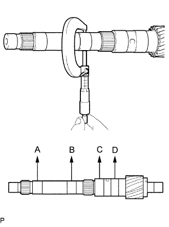 |
Using a micrometer, check the outer diameter of the intermediate shaft at each point shown in the illustration.
| 65. REMOVE BRAKE PLATE STOPPER SPRING |
 |
Remove the brake plate stopper spring from the transmission case.
| 66. REMOVE BRAKE DISC NO.4 |
 |
Remove the sleeve, 4 plates, 4 discs and flange from the transmission case.
| 67. INSPECT BRAKE DISC NO.4 |
|
Check whether the sliding surfaces of the discs, the plates, and the flange are worn or burnt.
If necessary, replace them.
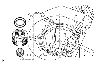
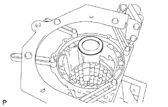
| 68. REMOVE REAR PLANETARY GEAR ASSEMBLY |
 |
Remove the rear planetary gear assembly from the transmission case.
 |
Remove the 2 thrust needle roller bearings from the rear planetary gear assembly.
 |
Remove the thrust bearing race No.9 from the transmission case.
| 69. INSPECT REAR PLANETARY GEAR ASSEMBLY |
 |
Using a feeler gauge, measure the rear planetary gear pinion thrust clearance.
 |
Using a dial indicator, measure the inside diameter of the rear planetary gear bushing.
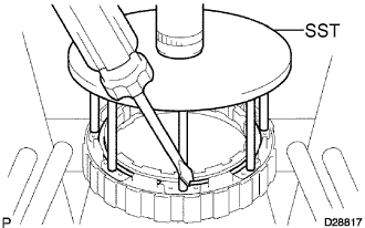
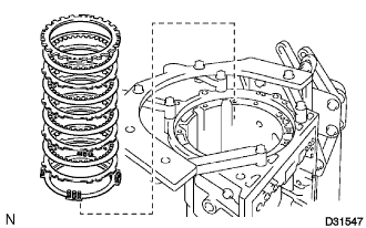
| 70. REMOVE 1ST AND REVERSE BRAKE RETURN SPRING SUB-ASSEMBLY |
 |
Place SST on the 1st and reverse brake return spring sub-assembly and compress the brake return spring.
Using SST, remove the snap ring and the brake return spring.
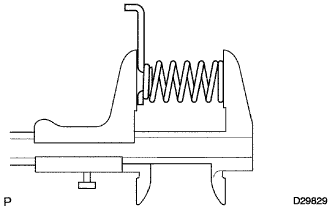
| 71. INSPECT 1ST AND REVERSE BRAKE RETURN SPRING SUB-ASSEMBLY |
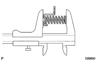 |
Using vernier calipers, measure the free length of the spring together with the spring seat.
| 72. REMOVE 1ST AND REVERSE BRAKE PISTON |
 |
Hold the 1st and reverse brake piston and blow compressed air (392 kPa, 4 kgf/cm2, 57 psi) into the transmission case to remove the brake piston.
Remove the brake apply tube from the piston.
Remove the O-ring from the brake piston.
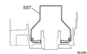
| 73. REMOVE BRAKE REACTION SLEEVE |
 |
Using SST, remove the reaction sleeve.
Remove the 2 O-rings from the reaction sleeve.
| 74. REMOVE BRAKE PISTON NO.4 |
 |
Using SST, remove the brake piston No.4.
Remove the 2 O-rings from the brake piston No.4.
