AUTOMATIC TRANSMISSION UNIT > REASSEMBLY |
| 1. BEARING POSITION |

| Mark | Front Race Diameter Inside/Outside | Thrust Bearing Diameter Inside/Outside | Rear Race Diameter Inside/Outside |
| A | 74.2 mm (2.921 in.) / 87.74 mm (3.454 in.) | 71.9 mm (2.831 in.) / 85.6 mm (3.370 in.) | - |
| B | 38.0 mm (1.496 in.) / 57.0 mm (2.244 in.) | 43.4 mm (1.709 in.) / 58.3 mm (2.295 in.) | - |
| C | - | 55.7 mm (2.193 in.) / 76.4 mm (3.008 in.) | - |
| D | - | - | 53.7 mm (2.114 in.) / 74.0 mm (2.913 in.) |
| E | 33.4 mm (1.315 in.) / 49.0 mm (1.929 in.) | 32.1 mm (1.264 in.) / 49.35 mm (1.943 in.) | 32.1 mm (1.264 in.) / 49.0 mm (1.929 in.) |
| F | - | 21.5 mm (0.847 in.) / 40.8 mm (1.606 in.) | - |
| G | - | 43.6 mm (1.717 in.) / 61.0 mm (2.402 in.) | 47.1 mm (1.854 in.) / 67.1 mm (2.642 in.) |
| H | 37 mm (1.45 in.) / 52.3 mm (2.059 in.) | 34.6 mm (1.362 in.) / 52.0 mm (2.047 in.) | - |
| I | 36.9 mm (1.453 in.) / 49.7 mm (1.957 in.) | 36.1 mm (1.421 in.) / 52.5 mm (2.067 in.) | 36.1 mm (1.421 in.) / 51.0 mm (2.007 in.) |
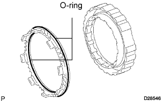
| 2. INSTALL BRAKE PISTON NO.4 |
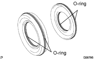 |
Coat 2 new O-rings with ATF, and install them to the brake reaction sleeve.
Coat 2 new O-rings with the ATF, and install them to the brake piston No.4.
Install the brake piston No.4 to the reaction sleeve.
| 3. INSTALL BRAKE REACTION SLEEVE |
 |
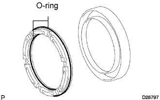
Coat a new O-ring with ATF, and install it to the reaction sleeve.
With the brake piston No.4 underneath (the rear side), install the brake reaction sleeve and the brake piston No.4 to the transmission case.
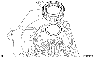
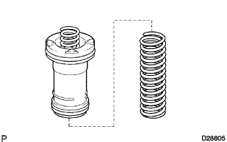
| 4. INSTALL 1ST AND REVERSE BRAKE PISTON |
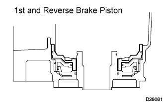 |
Coat a new O-ring with ATF.
Install the O-ring on the 1st and reverse brake piston.
With the spring seat of the piston facing upwards (the front side), place the piston in the transmission case.
 |
Place the brake return spring onto the brake piston No.4.
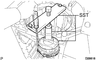
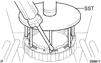
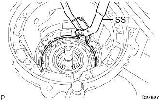
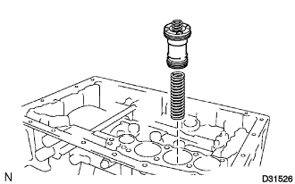
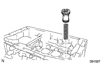
| 5. INSTALL 1ST AND REVERSE BRAKE RETURN SPRING SUB-ASSEMBLY |
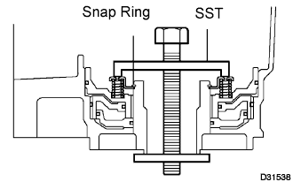 |
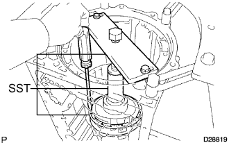
Place SST on the brake return spring, and compress the return spring.
Using SST, install the snap ring.
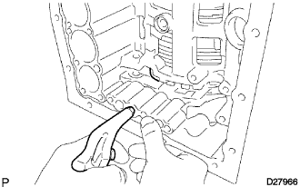
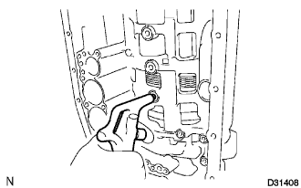
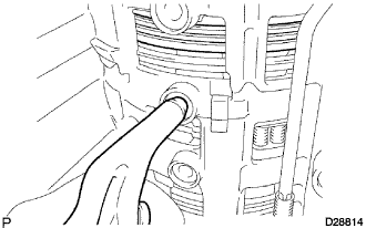
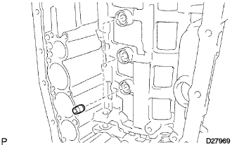
 |
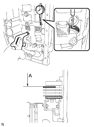
Install the brake apply tube with its protruding part fitting into the groove of the transmission case as shown in the illustration.
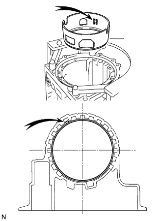
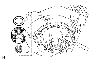
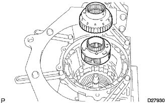
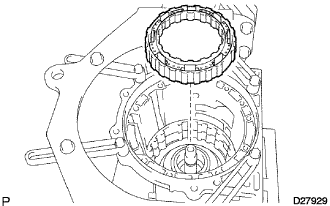
| 6. INSTALL REAR PLANETARY GEAR ASSEMBLY |
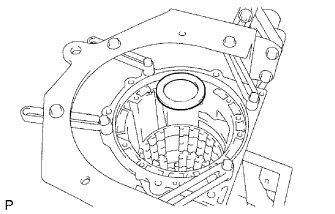 |
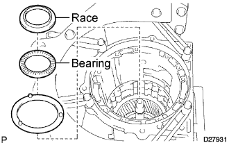
Install the thrust bearing race No.9.
| Inside | Outside | |
| Thrust bearing race | 47.1 mm (1.854 in.) | 67.1 mm (2.642 in.) |
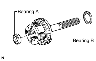 |
Install the 2 thrust needle roller bearings.
| Inside | Outside | |
| Bearing A | 21.5 mm (0.847 in.) | 40.8 mm (1.606 in.) |
| Bearing B | 43.6 mm (1.717 in.) | 61.0 mm (2.402 in.) |
 |
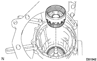
Install the rear planetary gear assembly.
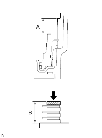
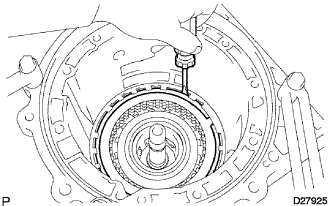
| 7. INSPECT PACK CLEARANCE OF FIRST AND REVERSE BRAKE PISTON |
 |
Make sure that the 1st and reverse brake piston moves smoothly while applying compressed air intermittently into the transmission case.
 |
Using vernier calipers, measure the level difference (length A) between the upper surface of the brake apply tube and the hitting surface of the brake flange No.4 at both ends across the 1st and reverse brake piston diameter, and calculate the average.
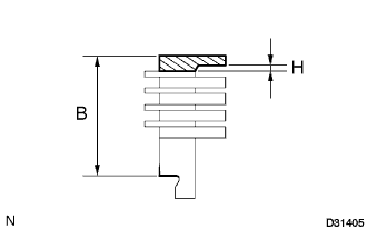 |
Using vernier calipers, measure the combined thickness (length B) of the brake flanges, the 4 brake plates No.4 and the 4 brake discs No.4 at both ends across the diameter, and calculate the average.
If the pack clearance is outside the standard, select and install a brake flange that brings the pack clearance to be within the standard.
| NO. | Thickness H | NO. | Thickness H |
| 0 | 0 mm (0 in.) | 8 | 0.8 mm (0.03150 in.) |
| 2 | 0.2 mm (0.00787 in.) | 10 | 1.0 mm (0.03937 in.) |
| 4 | 0.4 mm (0.01575 in.) | 12 | 1.2 mm (0.04724 in.) |
| 6 | 0.6 mm (0.02362 in.) | 14 | 1.4 mm (0.05512 in.) |
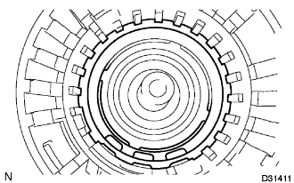
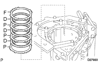
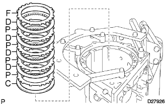
| 8. INSTALL BRAKE DISC NO.4 |
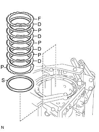 |
Install the sleeve, 4 plates, the 4 discs and the flange.
| 9. INSTALL BRAKE PLATE STOPPER SPRING |
 |
Install the brake plate stopper spring.
| 10. INSTALL REAR PLANETARY RING GEAR FLANGE SUB-ASSEMBLY |
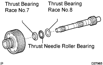 |
Install the thrust bearing race No.8, the thrust needle roller bearing, the thrust bearing race No.7 and the planetary ring gear flange to the intermediate shaft.
| Inside | Outside | |
| Thrust bearing race No.7 | 33.4 mm (1.315 in.) | 49.0 mm (1.929 in.) |
| Thrust needle roller bearing | 32.1 mm (1.264 in.) | 49.35 mm (1.943 in.) |
| Thrust bearing race No.8 | 32.1 mm (1.264 in.) | 49.0 mm (1.929 in.) |
| 11. INSTALL 1 WAY NO.3 CLUTCH ASSEMBLY |
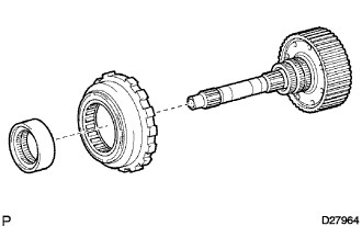 |
Install the 1 way No.3 clutch assembly and the 1 way clutch inner race to the intermediate shaft.
| 12. INSTALL INTERMEDIATE SHAFT |
 |
Install the intermediate shaft with the 1 way No.3 clutch assembly to the transmission case.
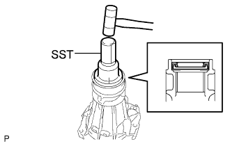
 |
Using SST, install the snap ring.
| 13. INSTALL CENTER PLANETARY GEAR ASSEMBLY |
 |
Install the center planetary gear assembly and the planetary sun gear to the transmission case.
Coat the thrust bearing race with petroleum jelly, and install it onto the center planetary ring gear.
| Inside | Outside | |
| Race | 53.7 mm (2.114 in.) | 74.0 mm (2.913 in.) |
| 14. INSTALL BRAKE PISTON NO.2 |
 |
Coat 2 new O-rings with ATF, and install them to the brake piston No.2.
Being careful not to damage the O-rings, press the brake piston No.2 into the brake cylinder No.2.
Install the brake piston No.2 to the transmission case.
 |
Check that the oil pressure apply hole of the brake cylinder No.2 aligns with the oil pressure apply hole of the transmission case.
| 15. INSTALL BRAKE DISC NO.2 |
 |
Install the 2 flanges, 3 plates, 4 discs and brake piston return spring.
 |
Using SST and a press, install the brake No.2 spring snap ring.
| 16. INSPECT PISTON STROKE OF BRAKE PISTON NO.2 |
Inspect the piston stroke of the brake piston No.2.
 |
Make sure that the brake piston No.2 moves smoothly while applying compressed air intermittently into the transmission case.
 |
Using SST and a dial indicator, measure the moving distance (distance A) of the clutch disc at both ends across the diameter while blowing air from the oil hole as shown in the illustration, and calculate the average.
If the piston stroke is outside the standard, select and install a brake flange that brings the piston stroke within the standard.
| No. | Thickness |
| 0 | 2.0 mm (0.079 in.) |
| 1 | 2.1 mm (0.083 in.) |
| 2 | 2.2 mm (0.087 in.) |
| 3 | 2.3 mm (0.091 in.) |
| 4 | 2.4 mm (0.094 in.) |
| 5 | 2.5 mm (0.098 in.) |
| 6 | 2.6 mm (0.102 in.) |
| 7 | 2.7 mm (0.106 in.) |
| 17. INSTALL BRAKE PISTON NO.1 |
 |
Coat 2 new O-rings with ATF, and install them on the brake piston No.1.
Be careful not to damage the O-rings. Press the brake piston No.1 into the brake cylinder No.1.
| 18. INSTALL BRAKE PISTON RETURN SPRING SUB-ASSEMBLY |
 |
Install the brake piston return spring and the brake piston No.1 with the brake cylinder No.1 to the transmission case.
 |
Check that the oil pressure apply hole of the brake cylinder No.1 aligns with the oil pressure apply hole of the transmission case.
| 19. INSTALL BRAKE PISTON RETURN SPRING SNAP RING |
 |
Using SST and a press, install the brake piston return spring snap ring.
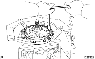
| 20. INSTALL CENTER PLANETARY RING GEAR |
Install the thrust needle roller bearing to the front planetary ring gear flange.
| Inside | Outside | |
| Thrust needle roller bearing | 55.7 mm (2.193 in.) | 76.4 mm (3.008 in.) |
 |
Install the center planetary ring gear and the front planetary ring gear flange on the front planetary ring gear.
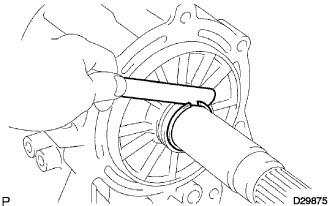
 |
Using a screwdriver, install the snap ring.
| 21. INSTALL FRONT PLANETARY RING GEAR |
 |
Install the front planetary ring gear to the transmission case.
| 22. INSTALL FRONT PLANETARY GEAR ASSEMBLY |
 |
Install the thrust needle roller bearing and the thrust washer.
Coat the thrust bearing race with petroleum jelly, and install it onto the front planetary ring gear.
| Inside | Outside | |
| Bearing | 43.4 mm (1.709 in.) | 58.3 mm (2.295 in.) |
| Race | 38.0 mm (1.496 in.) | 57.0 mm (2.244 in.) |
 |
Install the front planetary gear assembly and the 1 way clutch inner race to the transmission case.
| 23. INSPECT PISTON STROKE OF BRAKE PISTON NO.1 |
Inspect the piston stroke of the brake piston No.1.
 |
Make sure the brake piston No.1 moves smoothly while applying compressed air intermittently into the transmission case.
 |
Using vernier calipers, measure the level difference (length A) between the upper surface of the brake piston No.1 and the hitting surface of the brake flange No.1 at both ends across the brake piston No.1 diameter.
Using vernier calipers, measure the thickness (length B) of the brake flange, the 3 brake plates No.1 and the 3 brake discs No.1 altogether at both ends across the diameter, and calculate the average.
| No. | Thickness |
| 0 | 2.0 mm (0.079 in.) |
| 1 | 2.2 mm (0.087 in.) |
| 2 | 2.4 mm (0.094 in.) |
| 3 | 2.6 mm (0.102 in.) |
| 24. INSTALL BRAKE DISC NO.1 |
 |
Install the 3 plates, the 3 discs and the flange.
| 25. INSTALL 2ND BRAKE PISTON |
 |
Coat 2 new O-rings with ATF, and install them to the 2nd brake piston.
Be careful not to damage the O-rings. Press the 2nd brake piston into the 2nd brake cylinder.
 |
Using SST and a press, install the return spring with the snap ring.
| 26. INSTALL 2ND BRAKE CYLINDER |
 |
Install the 2nd brake cylinder to the transmission case.
 |
Check that the oil pressure apply hole of the brake cylinder aligns with the oil pressure apply hole of the transmission case.
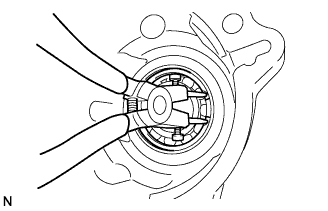
| 27. INSTALL 1 WAY CLUTCH ASSEMBLY |
 |
Install the 1 way clutch assembly and the thrust washer to the transmission case.
| 28. INSTALL 2ND BRAKE PISTON HOLE SNAP RING |
 |
Using SST, install the snap ring.
| 29. INSTALL 2ND BRAKE DISC SET |
 |
Install the cushion plate, flange, the 4 discs and the 4 plates to the transmission case.
| 30. INSTALL BRAKE NO.3 SNAP RING |
 |
Using a screwdriver, install the snap ring.
| 31. INSTALL 1 WAY NO.2 CLUTCH ASSEMBLY |
 |
Install the 1 way No.2 clutch assembly and washer No.2 to the clutch drum and input shaft.
| 32. INSTALL CLUTCH DRUM AND INPUT SHAFT |
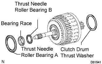 |
Install the thrust needle roller bearings and thrust washer.
Coat the race with petroleum jelly and install it onto the clutch drum and input shaft assembly.
| Inside | Outside | |
| Thrust needle roller bearing A | 71.9 mm (2.831 in.) | 85.6 mm (3.370 in.) |
| Thrust needle roller bearing B | 34.6 mm (1.362 in.) | 52.0 mm (2.047 in.) |
| Bearing Race | 37.0 mm (1.457 in.) | 52.3 mm (2.059 in.) |
 |
Install the clutch drum and input shaft onto the transmission case.
| 33. INSTALL OIL PUMP ASSEMBLY |
 |
Install the thrust bearing race No.1 to the front oil pump.
| Inside | Outside | |
| Race | 74.2 mm (2.921 in.) | 87.74 mm (3.454 in.) |
 |
Coat a new O-ring with ATF, and install it around the oil pump assembly.
Place the oil pump through the input shaft, and align the bolt holes of the oil pump assembly with the transmission case.
Hold the input shaft, and lightly press the oil pump body to slide the oil seal rings into the overdrive direct clutch drum.
 |
Install the 10 bolts.
| 34. INSTALL MANUAL VALVE LEVER SHAFT OIL SEAL |
 |
Using SST and a hammer, drive in 2 new oil seals.
Coat the oil seal lips with MP grease.
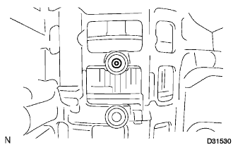
| 35. INSPECT INDIVIDUAL PISTON OPERATION |
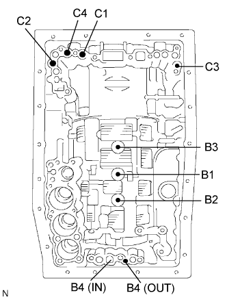 |
Check the operating sound while applying compressed air into the oil holes indicated in the illustration.
Clutch No.2 (C2)
Clutch No.4 (C4)
Clutch No.3 (C3)
Clutch No.1 (C1)
Brake No.3 (B3)
Brake No.1 (B1)
Brake No.2 (B2)
Brake No.4 (B4)
| 36. INSTALL MANUAL VALVE LEVER SUB-ASSEMBLY |
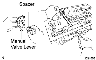 |
Install a new spacer to the manual valve lever.
Install the manual valve lever shaft to the transmission case through the manual valve lever.
 |
Using a hammer, drive in a new spring pin.
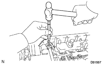 |
Align the manual valve lever indentation with the spacer hole, and stake them together with the punch.
Make sure that the shaft rotates smoothly.
| 37. INSTALL PARKING LOCK PAWL SHAFT |
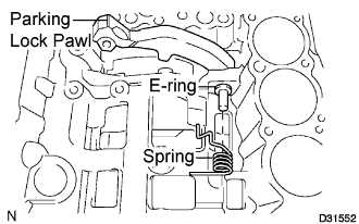 |
Install the E-ring to the shaft.
Install the parking lock pawl, the shaft and the spring.
| 38. INSTALL PARKING LOCK ROD SUB-ASSEMBLY |
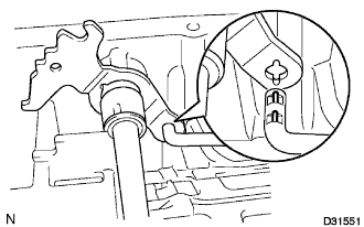 |
Connect the parking lock rod to the manual valve lever.
| 39. INSTALL PARKING LOCK PAWL BRACKET |
 |
Place the parking lock pawl bracket onto the transmission case and tighten the 3 bolts.
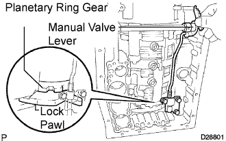 |
Shift the manual valve lever to the P position, and confirm the planetary gear is correctly locked up by the lock pawl.
| 40. INSTALL B-1 ACCUMULATOR VALVE |
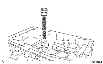  |
Install the 2 springs and the accumulator valve to the hole.
| Free length | Outer diameter | Color |
| 44.98 mm (1.7709 in.) | 11.30 mm (0.445 in.) | Natural |
| Free length | Outer diameter | Color |
| 46.36 mm (1.8252 in.) | 17.10 mm (0.6732 in.) | Natural |
| 41. INSTALL C-3 ACCUMULATOR PISTON |
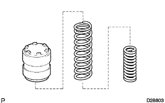
 |
Coat 2 new O-rings with ATF, and install them to the piston.
 |
Install the 2 springs and the accumulator piston to the hole.
| Free length | Outer diameter | Color |
| 44.0 mm (1.732 in.) | 14.0 mm (0.551 in.) | Yellow |
| Free length | Outer diameter | Color |
| 76.65 mm (3.0178 in.) | 20.10 mm (0.7913 in.) | Natural |
| 42. INSTALL B-3 ACCUMULATOR PISTON |
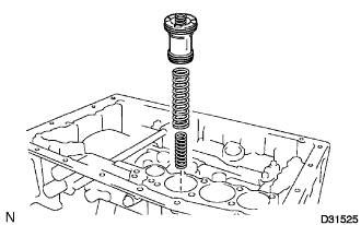
 |
Coat 2 new O-rings with ATF, and install them to the piston.
 |
Install the spring and the accumulator piston to the hole.
| Free length | Outer diameter | Color |
| 64.5 mm (2.539 in.) | 19.5 mm (0.768 in.) | Orange |
| 43. INSTALL C-2 ACCUMULATOR PISTON |
 |
Coat 2 new O-rings with ATF, and install them to the piston.
 |
Install the spring and the accumulator piston to the hole.
| Free length | Outer diameter | Color |
| 63.14 mm (2.4858 in.) | 16.0 mm (0.6299 in.) | Light Gray |
| 44. INSTALL CHECK BALL BODY |
 |
Install the check ball body and the spring.
| 45. INSTALL BRAKE DRUM GASKET |
 |
Install the 3 brake drum gaskets.
| 46. INSTALL TRANSAXLE CASE GASKET |
 |
Install the 3 transaxle case gaskets.
| 47. INSTALL TRANSMISSION VALVE BODY ASSEMBLY |
 |
Align the groove of the manual valve lever with the pin of the manual valve.
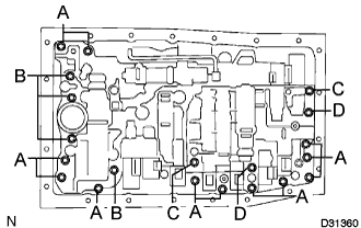 |
Install the 20 bolts.
 |
Install the detent spring and the detent spring cover with the bolt.
| 48. INSTALL TRANSMISSION WIRE |
 |
Install a new O-ring to the transmission wire.
Install the transmission wire.
Install the bolt.
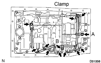 |
Connect the 9 solenoid connectors.
Install the ATF temperature sensor and clamp with the bolt.
Install the clamps with the 2 bolts.
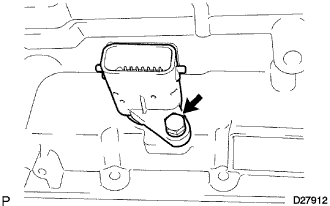
| 49. INSTALL VALVE BODY OIL STRAINER ASSEMBLY |
 |
Coat a new O-ring with ATF, and install it to the valve body oil strainer assembly.
Install the oil strainer with the 4 bolts.
| 50. INSTALL TRANSMISSION OIL CLEANER MAGNET |
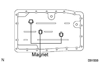 |
Install the 3 transmission oil cleaner magnets.
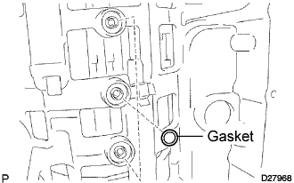
| 51. INSTALL AUTOMATIC TRANSMISSION OIL PAN SUB-ASSEMBLY |
Install a new gasket on the oil pan.
Install and tighten the 20 bolts.
Install a new gasket and the drain plug.
Install a new gasket and the over flow plug.
| 52. INSTALL AUTOMATIC TRANSMISSION EXTENSION HOUSING OIL SEAL |
 |
Using SST and a hammer, install a new oil seal.
| 53. INSTALL EXTENSION HOUSING DUST (ATM) DEFLECTOR |
 |
Using SST and a press, install a new extension housing dust deflector.
| 54. INSTALL ALL EXTENSION (ATM) HOUSING SUB-ASSEMBLY |
 |
Install the transmission case adapter radial ball bearing to the extension housing.
Using snap ring pliers, install a new snap ring.
 |
Install the thrust needle roller bearing and the 2 bearing races.
Using a snap ring expander, install a new snap ring.
 |
Using a feeler gauge, measure the clearance between the snap ring and the race.
| NO. | Thickness | NO. | Thickness |
| 1 | 3.80 mm (0.1496 in.) | 7 | 4.10 mm (0.1614 in.) |
| 2 | 3.85 mm (0.1516 in.) | 8 | 4.15 mm (0.1634 in.) |
| 3 | 3.90 mm (0.1535 in.) | 9 | 4.20 mm (0.1653 in.) |
| 4 | 3.95 mm (0.1555 in.) | 10 | 4.25 mm (0.1673 in.) |
| 5 | 4.00 mm (0.1575 in.) | 11 | 4.30 mm (0.1693 in.) |
| 6 | 4.05 mm (0.1594 in.) | 12 | 4.35 mm (0.1713 in.) |
Clean the threads of the bolts and the case with white gasoline.
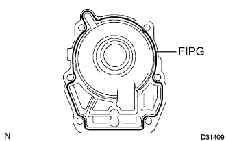 |
Apply FIPG to the extension housing as shown in the illustration.
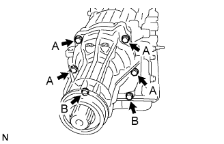 |
Install the extension housing with 6 new bolts.
| 55. INSTALL AUTOMATIC TRANSMISSION HOUSING |
 |
Clean the threads of the bolts and the case with white gasoline.
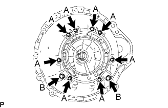
Install the transmission housing with the 10 bolts.
| 56. INSTALL AUTOMATIC TRANSMISSION BREATHER TUBE |
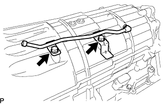 |
Install the breather tube.
Install the 2 bolts.
| 57. INSTALL TRANSMISSION REVOLUTION SENSOR |
 |
Coat 2 new O-rings with ATF, and install them to the transmission revolution sensors.
Install the 2 transmission revolution sensors.
Install the 2 bolts.
| 58. INSTALL TRANSMISSION OIL COOLER |
 |
Coat 2 new O-rings with ATF, and install them to the transmission oil cooler.
Coat 2 new O-rings with ATF, and install them to the spacer.
Install the spacer and transmission oil cooler with the 3 bolts.
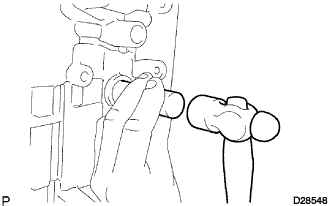
| 59. INSTALL PARK/NEUTRAL POSITION SWITCH ASSEMBLY |
 |
Install the park/neutral position switch onto the manual valve lever shaft, and temporarily install the adjusting bolt.
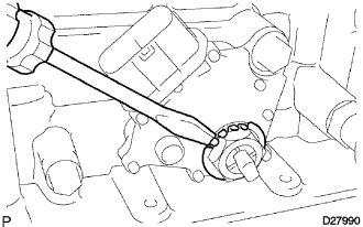
Install a new lock washer. Install and tighten the nut.
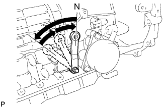 |
Using the control shaft lever, move the manual lever shaft back all the way and then forward 2 notches. It is now in neutral.
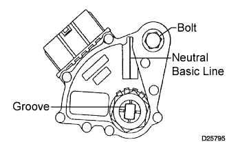 |
Align the neutral basic line with the switch groove as shown in the illustration, and tighten the adjusting bolt.
 |
Using a screwdriver, bend the tabs of the lock washer.
| 60. INSTALL TRANSMISSION CONTROL SHAFT LEVER RH |
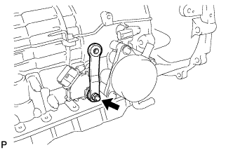 |
Install the control shaft lever RH, spring washer and the nut.
| 61. INSTALL TRANSAXLE CASE COVER UPPER |
Install the transaxle case cover upper with the 2 bolts.
