SHIFT SOLENOID VALVE > INSPECTION |
| 1. INSPECT SHIFT SOLENOID VALVE SL1 |
 |
Measure the resistance according to the value(s) in the table below.
| Tester Connection | Specified Condition 20°C (68°F) |
| 1 - 2 | 5.0 to 5.6 Ω |
Connect the positive (+) lead with a 21 W bulb to terminal 2 and the negative (-) lead to terminal 1 of the solenoid valve connector, and check operation of the valve.
| 2. INSPECT SHIFT SOLENOID VALVE S1 |
 |
Measure the resistance according to the value(s) in the table below.
| Tester Connection | Specified Condition 20°C (68°F) |
| Solenoid Connector (S1) - Solenoid Body (S1) | 11 to 15 Ω |
Connect the positive (+) lead to the terminal of the solenoid connector, and the negative (-) lead to the solenoid body, and check operation of the valve.
| 3. INSPECT SHIFT SOLENOID VALVE S2 |
 |
Measure the resistance according to the value(s) in the table below.
| Tester Connection | Specified Condition 20°C (68°F) |
| Solenoid Connector (S2) - Solenoid Body (S2) | 11 to 15 Ω |
Connect the positive (+) lead to the terminal of the solenoid connector, and the negative (-) lead to the solenoid body, and check operation of the valve.
| 4. INSPECT SHIFT SOLENOID VALVE S3 |
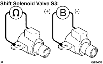 |
Measure the resistance according to the value(s) in the table below.
| Tester Connection | Specified Condition 20°C (68°F) |
| Solenoid Connector (S3) - Solenoid Body (S3) | 11 to 15 Ω |
Connect the positive (+) lead to the terminal of the solenoid connector, and the negative (-) lead to the solenoid body, and check operation of the valve.
| 5. INSPECT SHIFT SOLENOID VALVE S4 |
 |
Measure the resistance according to the value(s) in the table below.
| Tester Connection | Specified Condition 20°C (68°F) |
| Solenoid Connector (S4) - Solenoid Body (S4) | 11 to 15 Ω |
Connect the positive (+) lead to the terminal of the solenoid connector, and the negative (-) lead to the solenoid body, and check operation of the valve.
| 6. INSPECT SHIFT SOLENOID VALVE SL2 |
 |
Measure the resistance according to the value(s) in the table below.
| Tester Connection | Specified Condition 20°C (68°F) |
| 1 - 2 | 5.0 to 5.6 Ω |
Connect the positive (+) lead with a 21 W bulb to terminal 2 and the negative (-) lead to terminal 1 of the solenoid valve connector, and check operation of the valve.
| 7. INSPECT SHIFT SOLENOID VALVE SR |
 |
Measure the resistance according to the value(s) in the table below.
| Tester Connection | Specified Condition 20°C (68°F) |
| Solenoid Connector (SR) - Solenoid Body (SR) | 11 to 15 Ω |
Connect the positive (+) lead to the terminal of the solenoid connector, and the negative (-) lead to the solenoid body, and check operation of the valve.
| 8. INSPECT SHIFT SOLENOID VALVE SLT |
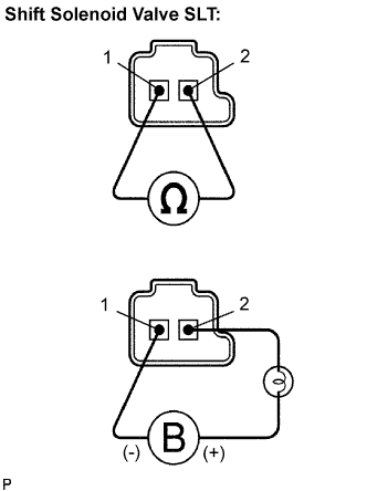 |
Measure the resistance according to the value(s) in the table below.
| Tester Connection | Specified Condition 20°C (68°F) |
| 1 - 2 | 5.0 to 5.6 Ω |
Connect the positive (+) lead with a 21 W bulb to terminal 2 and the negative (-) lead to terminal 1 of the solenoid valve connector, and check operation of the valve.
| 9. INSPECT SHIFT SOLENOID VALVE SLU |
 |
Measure the resistance according to the value(s) in the table below.
| Tester Connection | Specified Condition 20°C (68°F) |
| 1 - 2 | 5.0 to 5.6 Ω |
Connect the positive (+) lead with a 21 W bulb to terminal 2 and the negative (-) lead to terminal 1 of the solenoid valve connector, and check operation of the valve.
