CLUTCH DRUM AND INPUT SHAFT ASSEMBLY > DISASSEMBLY |
| 1. FIX CLUTCH DRUM AND INPUT SHAFT |
 |
Place the oil pump onto the torque converter clutch, and then place the clutch drum and input shaft onto the oil pump.
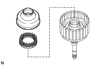
| 2. REMOVE REVERSE CLUTCH HUB SUB-ASSEMBLY |
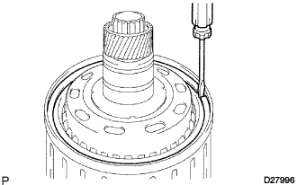 |
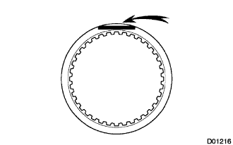
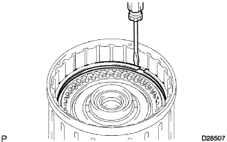
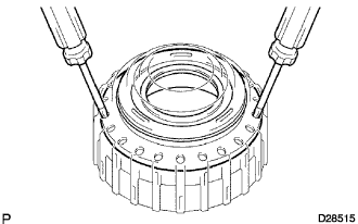
Using a screwdriver, remove the snap ring from the clutch drum and input shaft.
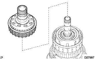 |
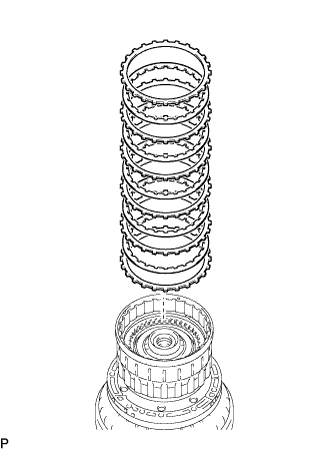
Remove the reverse clutch hub sub-assembly with the reverse clutch reaction sleeve, the clutch cushion plate, the reverse clutch flange, the 5 rear clutch discs, and the 4 clutch plates from the forward clutch hub.
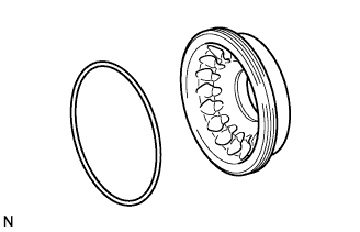
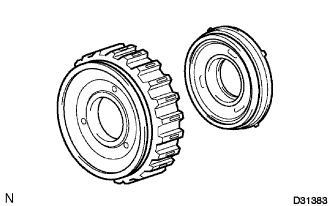
| 3. REMOVE REVERSE CLUTCH REACTION SLEEVE |
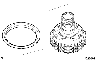 |
Remove the reverse clutch reaction sleeve from the reverse clutch hub sub-assembly.
| 4. REMOVE REAR CLUTCH DISC |
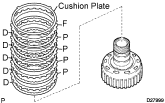 |
Remove the clutch cushion plate, the reverse clutch flange, the 4 plates and the 5 discs from the reverse clutch hub.
| 5. INSPECT REAR CLUTCH DISC |
 |
Check whether the sliding surfaces of the discs, the plates, and the flange are worn or burnt.
If necessary, replace them.
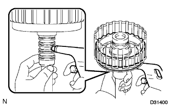
| 6. INSPECT REVERSE CLUTCH HUB SUB-ASSEMBLY |
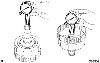
Inspect the pack clearance of the reverse clutch hub sub-assembly.
Using a dial indicator, measure the reverse clutch piston stroke (distance A) and the moving distance (distance B) of the reverse clutch flange at both ends across the diameter while blowing air (392 kPa, 4 kgf/cm2, 57 psi) from the oil hole as shown in the illustration, and calculate the average.

If the pack clearance is outside the standard, select and install a clutch flange that brings the pack clearance within the standard.
| No. | Thickness |
| 0 | 2.4 mm (0.094 in.) |
| 1 | 2.5 mm (0.098 in.) |
| 2 | 2.6 mm (0.102 in.) |
| 3 | 2.7 mm (0.106 in.) |
| 4 | 2.8 mm (0.110 in.) |
| 5 | 2.9 mm (0.114 in.) |
| 6 | 3.0 mm (0.118 in.) |
| 7 | 3.1 mm (0.122 in.) |
| 8 | 3.2 mm (0.126 in.) |
| 9 | 3.3 mm (0.130 in.) |
| A | 3.4 mm (0.134 in.) |
| B | 3.5 mm (0.138 in.) |
| 7. REMOVE FORWARD CLUTCH HUB SUB-ASSEMBLY |
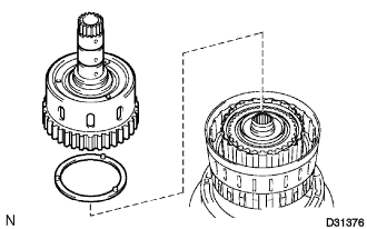 |
Remove the forward clutch hub sub-assembly and thrust washer from the clutch drum assembly.
 |
Remove the 2 thrust needle roller bearings and the thrust bearing race from the forward clutch hub sub-assembly.
| 8. INSPECT FORWARD CLUTCH HUB SUB-ASSEMBLY |
 |
Using a dial indicator, measure the inside diameter of the forward clutch hub bushing.
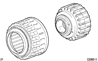
| 9. REMOVE COAST CLUTCH HUB SUB-ASSEMBLY |
 |
Remove the coast clutch hub sub-assembly from the clutch drum sub-assembly.
| 10. INSPECT 1 WAY NO.4 CLUTCH ASSEMBLY |
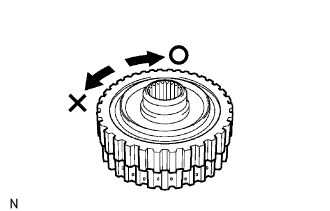 |
Hold the coast clutch hub and turn the 1 way clutch assembly.
Check that the 1 way clutch assembly turns freely clockwise and locks counterclockwise.
If there is a problem with the 1 way clutch, replace it.
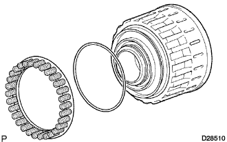
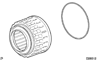
| 11. REMOVE 1 WAY NO.4 CLUTCH ASSEMBLY |
 |
Remove the 1 way No.4 clutch assembly and the clutch hub thrust washer from the coast clutch hub.
| 12. REMOVE FORWARD CLUTCH HUB CLUTCH DISC |
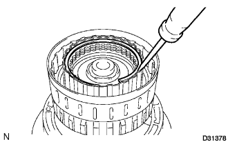 |
Using a screwdriver, remove the hole snap ring.
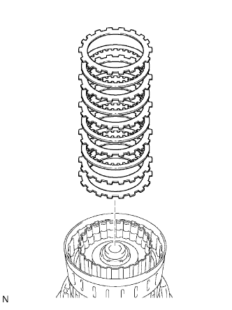 |
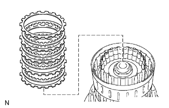
Remove the flange, cushion plate, 4 discs and 5 plates from the input shaft.
| 13. INSPECT FORWARD CLUTCH HUB CLUTCH DISC |
|
Check whether the sliding surfaces of the discs, the plates, and the flange are worn or burnt.
If necessary, replace them.
| 14. REMOVE COAST CLUTCH DISC |
 |
Using a screwdriver, remove the hole snap ring.
 |
Remove the flange, the 4 discs and the 4 plates from the input shaft.
| 15. INSPECT COAST CLUTCH DISC |
|
Check whether the sliding surfaces of the discs, the plates, and the flange are worn or burnt.
If necessary, replace them.
| 16. REMOVE INPUT SHAFT |
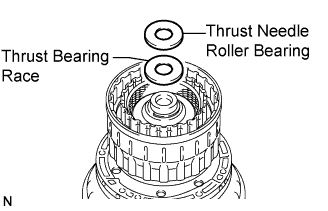 |
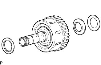
Remove the thrust needle roller bearing and the thrust bearing race from the input shaft.
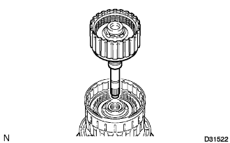 |
Remove the input shaft from the clutch drum.
 |
Remove the thrust needle roller bearing and thrust bearing race from the clutch drum.
| 17. REMOVE INPUT SHAFT OIL SEAL RING |
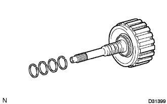 |
Remove the 4 oil seal rings from the input shaft.
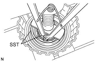
| 18. REMOVE CLUTCH BALANCER NO.1 |
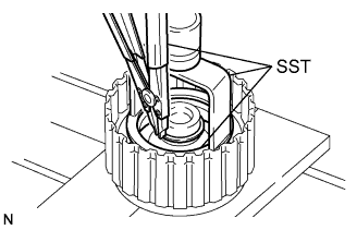 |
Place SST on the clutch balancer No.1, and compress the return spring with a press.
Using SST and press, remove the snap ring.
 |
Remove the clutch balancer No.1 and the forward clutch return spring from the input shaft.
 |
Remove the D-ring from the clutch balancer No.1.
| 19. INSPECT FORWARD CLUTCH RETURN SPRING SUB-ASSEMBLY |
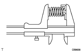 |
Using vernier calipers, measure the free length of the spring together with the spring seat.
| 20. REMOVE FORWARD CLUTCH PISTON SUB-ASSEMBLY |
 |
Holding the forward clutch piston by hand, apply compressed air (392 kPa, 4.0 kgf/cm2, 57 psi) to the input shaft to remove the forward clutch piston.
 |
Remove the coast clutch piston from the forward clutch piston.
Remove the O-ring from the forward clutch piston.
| 21. REMOVE REVERSE CLUTCH FLANGE |
 |
Remove the reverse clutch flange from the clutch drum assembly.
| 22. REMOVE DIRECT CLUTCH DISC |
 |
Using a screwdriver, remove the 2 hole snap rings from the clutch drum assembly.
 |
Remove the direct clutch flange, the 5 plates and the 5 discs from the clutch drum assembly.
| 23. INSPECT DIRECT CLUTCH DISC |
|
Check whether the sliding surfaces of the discs, the plates, and the flange are worn or burnt.
If necessary, replace them.
| 24. REMOVE CLUTCH BALANCER NO.3 |
 |
Place SST on the clutch balancer No.3, and compress the return spring with a press.
Using SST and press, remove the snap ring.
Remove the clutch balancer No.3.
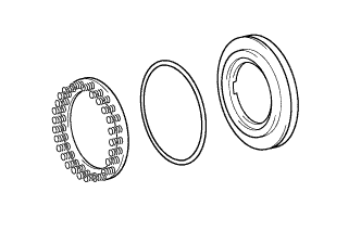
| 25. REMOVE REVERSE CLUTCH RETURN SPRING SUB-ASSEMBLY |
 |
Remove the reverse clutch return spring and the O-ring from the reverse clutch piston.
| 26. INSPECT REVERSE CLUTCH RETURN SPRING SUB-ASSEMBLY |
|
Using vernier calipers, measure the free length of the spring together with the spring seat.
| 27. REMOVE REVERSE CLUTCH PISTON SUB-ASSEMBLY |
 |
Remove the reverse clutch piston sub-assembly from the clutch drum sub-assembly.
 |
Remove the O-ring from the reverse clutch piston sub-assembly.
 |
Remove the O-ring from the clutch drum sub-assembly.
| 28. REMOVE DIRECT CLUTCH PISTON SUB-ASSEMBLY |
 |
Place SST on the direct clutch piston, and compress the return spring with a press.
Using SST and press, remove the snap ring.
 |
Remove the clutch balancer No.2 and the direct clutch return spring sub-assembly.
Remove the O-ring from the clutch balancer No.2.
 |
Using 2 screwdrivers, remove the direct clutch piston sub-assembly from the clutch drum.
 |
Remove the 2 O-rings from the direct clutch piston sub-assembly.
| 29. INSPECT DIRECT CLUTCH RETURN SPRING SUB-ASSEMBLY |
|
Using vernier calipers, measure the free length of the spring together with the spring seat.
