CLUTCH DRUM AND INPUT SHAFT ASSEMBLY > REASSEMBLY |
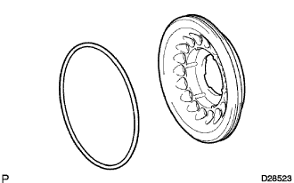
| 1. INSTALL DIRECT CLUTCH PISTON SUB-ASSEMBLY |
 |
Coat 2 new O-rings with ATF, and install them in the direct clutch piston.
 |
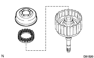
Install the clutch balancer No.2 and the direct clutch return spring to the direct clutch piston sub-assembly.
Press the direct clutch piston into the clutch drum by hands.
 |
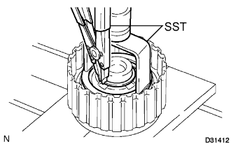
Place SST on the direct clutch piston, and compress the return spring with a press.
Install the snap ring with a snap ring expander.
 |
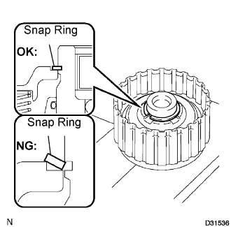
Set the end gap of the snap ring in the piston as shown in the illustration.
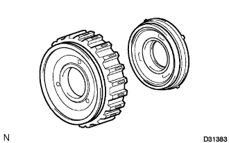
| 2. INSTALL REVERSE CLUTCH PISTON SUB-ASSEMBLY |
 |
Coat a new O-ring with ATF, and install it on the clutch drum sub-assembly.
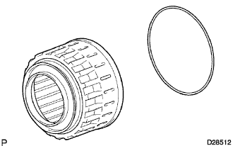 |
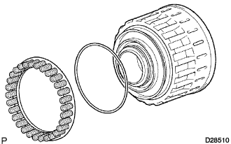
Coat a new O-ring with ATF, and install it on the reverse clutch piston sub-assembly.
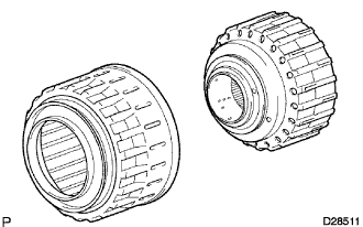 |
Press the clutch drum sub-assembly into the reverse clutch piston with both hands.
| 3. INSTALL REVERSE CLUTCH RETURN SPRING SUB-ASSEMBLY |
Coat a new O-ring with ATF, and install it on the reverse clutch piston sub-assembly.
 |
Install the reverse clutch return spring onto the reverse clutch piston sub-assembly.
| 4. INSTALL CLUTCH BALANCER NO.3 |
 |
Install the clutch balancer No.3 to the reverse clutch return spring.
Place SST on the clutch balancer No.3, and compress the clutch balancer with a press.
Install the snap ring with a snap ring expander.
 |
Set the end gap of the snap ring in the piston as shown in the illustration.
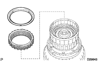
| 5. INSTALL DIRECT CLUTCH DISC |
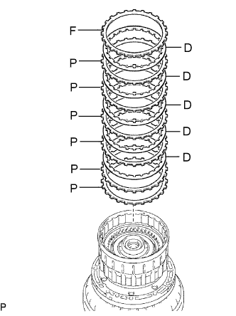 |
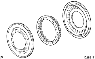
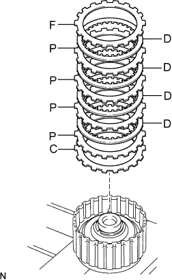
Install the reverse clutch flange, the 6 plates and the 5 discs on the clutch drum sub-assembly.
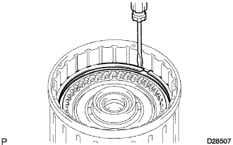 |
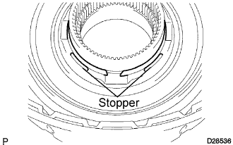
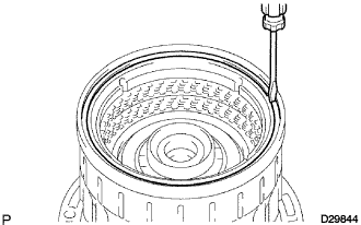
Using a screwdriver, install the 2 hole snap rings on the clutch drum sub-assembly.
| 6. INSPECT PACK CLEARANCE OF DIRECT CLUTCH |
 |
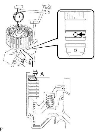
Inspect the pack clearance of the direct clutch.
Using a dial indicator, measure the moving distance (distance A) of the clutch flange at both ends across the diameter while blowing air to the oil hole as shown in the illustration, and calculate the average.
If the pack clearance is outside the standard, select and install a clutch flange that brings the pack clearance within the standard.
| No. | Thickness |
| 0 | 3.0 mm (0.118 in.) |
| 1 | 3.1 mm (0.122 in.) |
| 2 | 3.2 mm (0.126 in.) |
| 3 | 3.3 mm (0.130 in.) |
| 4 | 3.4 mm (0.134 in.) |
| 5 | 3.5 mm (0.138 in.) |
| 6 | 3.6 mm (0.142 in.) |
| 7 | 3.7 mm (0.146 in.) |
| 8 | 3.8 mm (0.150 in.) |
| 7. INSTALL REVERSE CLUTCH FLANGE |
 |
Install the reverse clutch flange to the clutch drum sub-assembly.
| 8. INSTALL REVERSE CLUTCH REACTION SLEEVE |
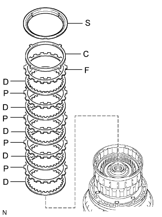 |
Install the reverse clutch reaction sleeve, the clutch cushion plate, the reverse clutch flange, the 5 reverse clutch discs, and the 4 clutch plates to the reverse clutch hub.
Using a screwdriver, install the hole snap ring.
| 9. INSPECT PACK CLEARANCE OF REVERSE CLUTCH |
Inspect the pack clearance of the reverse clutch hub sub-assembly.
Using a dial indicator, measure the reverse clutch piston stroke (distance A) and the moving distance (distance B) of the reverse clutch flange at both ends across the diameter while blowing air (392 kPa, 4 kgf/cm2, 57 psi) from the oil hole as shown in the illustration, and calculate the average.

If the pack clearance is outside the standard, select and install a clutch flange that brings the pack clearance within the standard.
| No. | Thickness |
| 0 | 2.8 mm (0.110 in.) |
| 1 | 2.9 mm (0.114 in.) |
| 2 | 3.0 mm (0.118 in.) |
| 3 | 3.1 mm (0.122 in.) |
| 4 | 3.2 mm (0.126 in.) |
| 5 | 3.3 mm (0.130 in.) |
| 6 | 3.4 mm (0.134 in.) |
| 7 | 3.5 mm (0.138 in.) |
| 8 | 3.6 mm (0.142 in.) |
| 9 | 3.7 mm (0.146 in.) |
| A | 3.8 mm (0.150 in.) |
| 10. REMOVE REVERSE CLUTCH REACTION SLEEVE |
 |
Using a screwdriver, remove the snap ring from the clutch drum assembly.
 |
Remove the reverse clutch reaction sleeve, the clutch cushion plate, the reverse clutch flange, the 5 reverse clutch discs, and the 4 clutch plates from the reverse clutch hub sub-assembly.
| 11. INSTALL FORWARD CLUTCH PISTON SUB-ASSEMBLY |
 |
Install the coast clutch piston to the forward clutch piston.
Install the O-ring to the forward clutch.
Install the forward clutch piston sub-assembly to the input shaft.
| 12. INSTALL CLUTCH BALANCER NO.1 |
 |
Coat a new O-ring with ATF and install it on the clutch balancer No.1.
 |
Install the clutch balancer No.1 and the forward clutch return spring sub-assembly.
 |
Place SST on the clutch balancer No.1, and compress the return spring with a press.
Install the snap ring with a snap ring expander.
 |
Set the end gap of the snap ring in the piston as shown in the illustration.
| 13. INSTALL COAST CLUTCH DISC |
 |
Install the flange, the 3 discs and the 3 plates to the forward clutch piston.
Using a screwdriver, install the hole snap ring.
| 14. INSPECT PACK CLEARANCE OF COAST CLUTCH |
 |
Inspect the pack clearance of the coast clutch hub sub-assembly.
Using a dial indicator, measure the moving distance (distance A) of the clutch flange at both ends across the diameter while blowing air from the oil hole as shown in the illustration, and calculate the average.
If the pack clearance is outside the standard, select and install a clutch flange that brings the pack clearance within the standard.
| No. | Thickness |
| 0 | 3.0 mm (0.118 in.) |
| 1 | 3.1 mm (0.122 in.) |
| 2 | 3.2 mm (0.126 in.) |
| 3 | 3.3 mm (0.130 in.) |
| 4 | 3.4 mm (0.134 in.) |
| 5 | 3.5 mm (0.138 in.) |
| 6 | 3.6 mm (0.142 in.) |
| 7 | 3.7 mm (0.146 in.) |
| 8 | 3.8 mm (0.150 in.) |
| 9 | 3.9 mm (0.154 in.) |
| 15. INSTALL FORWARD CLUTCH HUB CLUTCH DISC |
 |
Install the flange, the 4 discs, the 4 plates and cushion plate to the input shaft assembly.
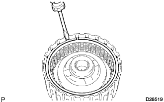 |
Using a screwdriver, install the hole snap ring.
 |
Install the thrust needle roller bearing and the thrust bearing race.
| Inside | Outside | |
| Thrust needle roller bearing | 21.3 mm (0.839 in.) | 41.1 mm (1.618 in.) |
| Thrust bearing race No.2 | 22.6 mm (0.890 in.) | 44.8 mm (1.764 in.) |
| 16. INSTALL INPUT SHAFT OIL SEAL RING |
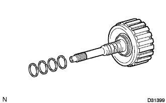 |
Coat 4 new oil seal rings with ATF.
Squeeze the ends of the 4 oil seal rings, and then install them to the input shaft groove.
| 17. INSPECT PACK CLEARANCE OF FORWARD CLUTCH |
Inspect the pack clearance of the forward clutch.
 |
Using a dial indicator, measure the moving distance (distance A) of the clutch flange at both ends across the diameter while blowing air from the oil hole as shown in the illustration, and calculate the average.
If the pack clearance is outside the standard, select and install a clutch flange that brings the pack clearance within the standard.
| No. | Thickness |
| 0 | 3.0 mm (0.118 in.) |
| 1 | 3.1 mm (0.122 in.) |
| 2 | 3.2 mm (0.126 in.) |
| 3 | 3.3 mm (0.130 in.) |
| 4 | 3.4 mm (0.134 in.) |
| 5 | 3.5 mm (0.138 in.) |
| 6 | 3.6 mm (0.142 in.) |
| 7 | 3.7 mm (0.146 in.) |
| 8 | 3.8 mm (0.150 in.) |
| 9 | 3.9 mm (0.154 in.) |
| A | 4.0 mm (0.158 in.) |
| 18. INSTALL INPUT SHAFT ASSEMBLY |
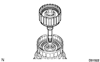 |
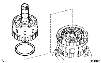
Install the input shaft assembly to the clutch drum.
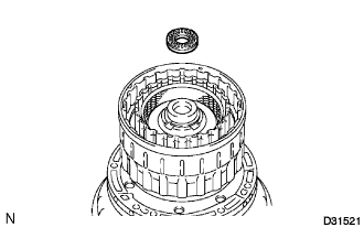 |
Install the thrust needle roller bearing to the clutch drum assembly.
| Inside | Outside | |
| Thrust needle roller bearing | 21.3 mm (0.839 in.) | 41.1 mm (1.618 in.) |
| 19. INSTALL COAST CLUTCH HUB SUB-ASSEMBLY |
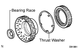 |
Install the underdrive 1 way clutch, clutch hub thrust washer and the input shaft rear thrust bearing race to the coast clutch hub.
| Inside | Outside | |
| Input shaft rear thrust bearing race | 22.6 mm (0.890 in.) | 44.8 mm (1.764 in.) |
 |
Install the coast clutch hub sub-assembly to the clutch drum assembly.
| 20. INSTALL FORWARD CLUTCH HUB SUB-ASSEMBLY |
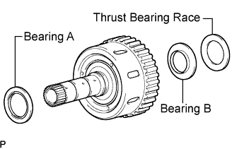 |
Install the 2 thrust needle roller bearings and thrust bearing race No.3 to the forward clutch hub sub-assembly.
| Inside | Outside | |
| Bearing A | 42.5 mm (1.673 in.) | 61.2 mm (2.409 in.) |
| Bearing B | 35.6 mm (1.402 in.) | 56.6 mm (2.228 in.) |
| Thrust bearing race No.3 | 35.6 mm (1.402 in.) | 56.6 mm (2.228 in.) |
 |
Install the clutch hub thrust washer and forward clutch hub sub-assembly to the clutch drum assembly.
| 21. INSTALL REAR CLUTCH DISC |
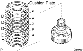 |
Install the clutch cushion plate, the reverse clutch flange, the 4 plates and the 5 discs to the reverse clutch hub.
| 22. INSTALL REVERSE CLUTCH REACTION SLEEVE |
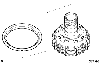 |
Install the reverse clutch reaction sleeve to the reverse clutch hub.
| 23. INSTALL REVERSE CLUTCH HUB SUB-ASSEMBLY |
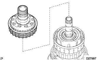 |
Install the reverse clutch hub sub-assembly, the reverse clutch reaction sleeve, the clutch cushion plate, the reverse clutch flange, the 5 reverse clutch discs, and the clutch plates to the clutch drum assembly.
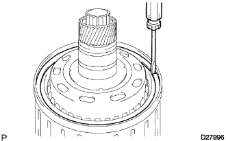 |
Using a screwdriver, install the snap ring on the clutch drum and the input shaft assembly.
