DTC P2118 Throttle Actuator Control Motor Current Range / Performance |
| DTC No. | DTC Detection Conditions | Trouble Areas |
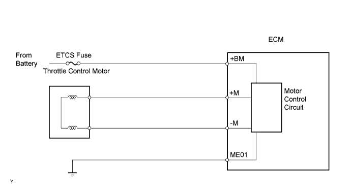
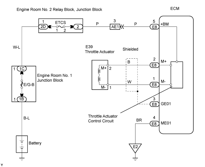
| P2118 | Open in ETCS power source (+BM) circuit (1 trip detection logic) |
|
| 1.INSPECT FUSE (ETCS) |
 |
Remove the ETCS fuse from the engine room No. 2 relay block.
Measure the resistance of the fuse.
|
| ||||
| OK | |
| 2.READ DATA LIST (+BM VOLTAGE) |
 |
Connect the intelligent tester to the DLC3.
Turn the engine switch on (IG).
Enter the following menus: Powertrain / Engine / Data List / Primary / +BM Voltage.
|
| ||||
| NG | |
| 3.CHECK WIRE HARNESS (ECM - ETCS FUSE, ETCS FUSE - BATTERY) |
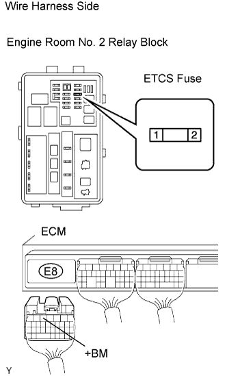 |
Remove the ETCS fuse from the engine room No. 2 relay block, junction block.
Disconnect the E8 ECM connector.
Measure the resistance of the wire harness side connectors.
| Tester Connection | Specified Condition |
| Relay block ETCS fuse terminal 1 - Battery positive (+) terminal | Below 1 Ω |
| Relay block ETCS fuse terminal 2 - E8-5 (+BM) | Below 1 Ω |
| Relay block ETCS fuse terminal 1 or Battery positive (+) terminal - Body ground | 10 kΩ or higher |
| Relay block ETCS fuse terminal 2 or E8-5 (+BM) - Body ground | 10 kΩ or higher |
|
| ||||
| OK | ||
| ||
