WIPER AND WASHER SYSTEM > Headlight Cleaner Switch Circuit |
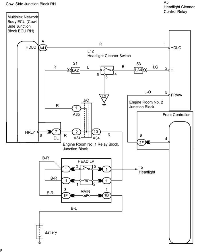
| 1.CHECK COWL SIDE JUNCTION BLOCK RH (HDLO SIGNAL) |
 |
Measure the voltage of the connector.
| Tester Connection | Condition | Specified Condition |
| A41-4 (HDLO) - Body ground | Engine switch on (IG) and light control switch OFF | 10 to 14 V |
| A41-4 (HDLO) - Body ground | Engine switch on (IG) and light control switch in HEAD position | Below 1 V |
|
| ||||
| OK | |
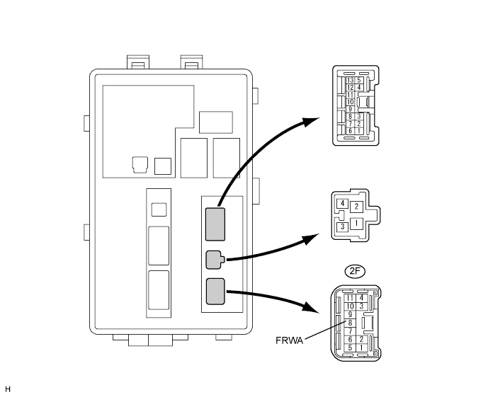
| 2.INSPECT ENGINE ROOM NO. 2 JUNCTION BLOCK (FRONT WINDOW WASHER SIGNAL) |
Measure the voltage of the connector.
| Tester Connection | Condition | Specified Condition |
| 2F-8 (FRWA) - Body ground | Engine switch on (IG) and front washer is stopped | 10 to 14 V |
| 2F-8 (FRWA) - Body ground | Engine switch on (IG) and front washer is operated | Below 1 V |
|
| ||||
| OK | |
| 3.CHECK WIRE HARNESS (HEADLIGHT CLEANER CONTROL RELAY - BATTERY AND BODY GROUND) |
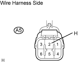 |
Disconnect the A5 headlight cleaner control relay connector.
Measure the resistance of the connector.
| Tester Connection | Condition | Specified Condition |
| A5-2 (H) - Body ground | Headlight cleaner switch OFF (not pushed) | 10 kΩ or higher |
| A5-2 (H) - Body ground | Headlight cleaner switch ON (pushed) | Below 1 Ω |
|
| ||||
| OK | ||
| ||
| 4.INSPECT COWL SIDE JUNCTION BLOCK RH |
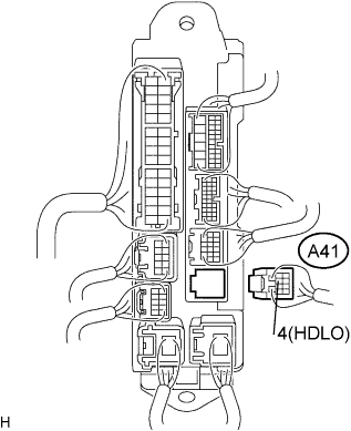 |
Disconnect the A41 cowl side junction block RH connector.
Measure the voltage of the connector.
| Tester Connection | Condition | Specified Condition |
| A41-4 (HDLO) - Body ground | Engine switch off | Below 1 V |
| A41-4 (HDLO) - Body ground | Engine switch on (IG) | 10 to 14 V |
|
| ||||
| OK | ||
| ||
| 5.CHECK WIRE HARNESS (HEADLIGHT CLEANER CONTROL RELAY - COWL SIDE JUNCTION BLOCK RH) |
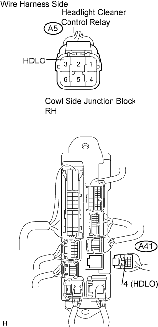 |
Disconnect the A5 relay connector.
Disconnect the A41 junction block connector.
Measure the resistance of the wire harness side connectors.
| Tester Connection | Condition | Specified Condition |
| A5-3 (HDLO) - A41-4 (HDLO) | Always | Below 1 Ω |
| A5-3 (HDLO) - Body ground | Always | 10 kΩ or higher |
|
| ||||
| OK | ||
| ||
| 6.CHECK WIRE HARNESS (HEADLIGHT CLEANER CONTROL RELAY - ENGINE ROOM JUNCTION BLOCK) |
Disconnect the A5 relay connector.
Disconnect the 2F junction block connector.
Measure the resistance of the wire harness side connectors.

| Tester Connection | Condition | Specified Condition |
| A5-5 (FRWA) - F2-8 (FRWA) | Always | Below 1 Ω |
| A5-5 (FRWA) - Body ground | Always | 10 kΩ or higher |
|
| ||||
| OK | ||
| ||
| 7.INSPECT INTEGRATION CONTROL & PANEL ASSEMBLY (HEADLIGHT CLEANER SWITCH) |
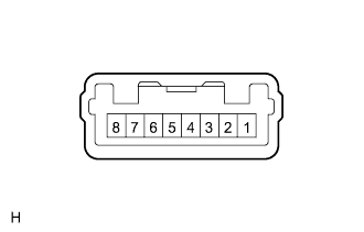 |
Remove the integration control & panel assembly.
Measure the resistance of the connector.
| Tester Connection | Condition | Specified Condition |
| 3 - 4 | Integration control & panel ON (not pushed) | 10 kΩ or higher |
| 3 - 4 | Integration control & panel OFF (pushed) | Below 1 Ω |
|
| ||||
| OK | ||
| ||
