WIPER AND WASHER SYSTEM > Wiper Motor Power Source Circuit |
| 1.CHECK COWL SIDE JUNCTION BLOCK LH (COWL SIDE JUNCTION BLOCK ECU LH) |
 |
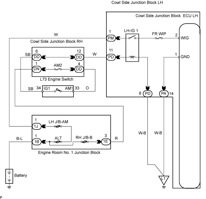
Measure the voltage of the connectors.
| Tester Connection | Condition | Specified Condition |
| PD-11 - PD-8 | Engine switch off | Below 1 V |
| PD-11 - PD-8 | Engine switch on (IG) | 10 to 14 V |
| PM-1 (WIG) - PA-14 (GND) | Engine switch off | Below 1 V |
| PM-1 (WIG) - PA-14 (GND) | Engine switch on (IG) | 10 to 14 V |
|
| ||||
| OK | ||
| ||
| 2.CHECK WIRE HARNESS (COWL SIDE JUNCTION BLOCK LH - BODY GROUND) |
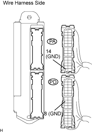 |
Disconnect the PD and PA junction block connectors.
Measure the resistance of the wire harness side connectors.
| Tester Connection | Condition | Specified Condition |
| PA-14 (GND) - Body ground | Always | Below 1 Ω |
| PD-8 - Body ground | Always | Below 1 Ω |
|
| ||||
| OK | ||
| ||
