NAVIGATION SYSTEM > Navigation ECU Power Source Circuit |
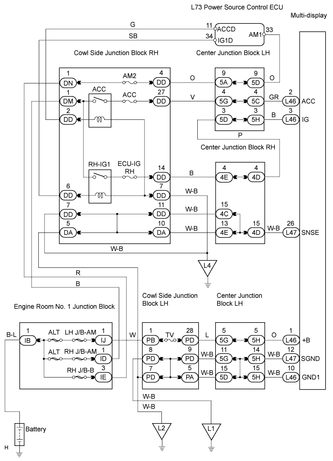
| 1.CHECK MULTI-DISPLAY POWER SOURCE CIRCUIT |
| NEXT | |
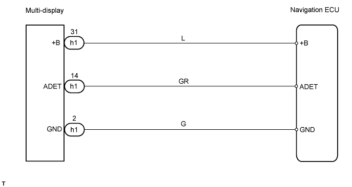
| 2.CHECK MULTI-DISPLAY |
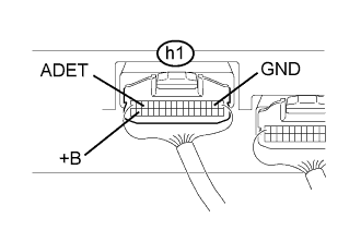 |
Measure the voltage of the connector.
| Tester Connection | Condition | Specified Condition |
| h1-31 (+B) - Body ground | Always | 10 to 14 V |
| h1-14 (ADET) - Body ground | Engine switch on (ACC) | 10 to 14 V |
Measure the resistance of the connector.
| Tester Connection | Condition | Specified Condition |
| h1-2 (GND) - Body ground | Always | Below 1 Ω |
|
| ||||
| OK | ||
| ||
