NAVIGATION SYSTEM > Parking Brake Switch Circuit |
| 1.CHECK BRAKE WARNING LIGHT |
Check that the brake warning light illuminates when the parking brake pedal is depressed, and goes off when the parking brake pedal is released.
|
| ||||
| NG | |
| 2.INSPECT PARKING BRAKE SWITCH |
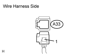 |
Disconnect the A33 switch connector.
Measure the resistance of the wire harness side connector.
| Tester Connection | Switch Condition | Specified Condition |
| Switch connector - Switch body | Pushed | Below 1 Ω |
| Switch connector - Switch body | Not pushed | 10 kΩ or higher |
|
| ||||
| OK | |
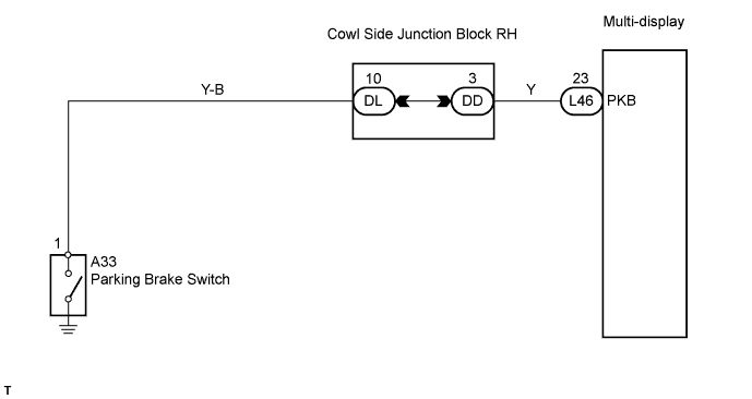
| 3.CHECK WIRE HARNESS (PARKING BRAKE SWITCH - MULTI-DISPLAY) |
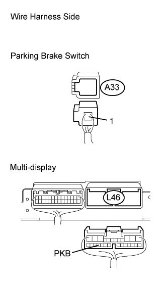 |
Disconnect the L46 multi-display connector.
Disconnect the A33 switch connector.
Measure the resistance of the wire harness side connectors.
| Tester Connection | Condition | Specified Condition |
| L46-23 (PKB) - A33-1 | Always | Below 1 Ω |
| L46-23 (PKB) - Body ground | Always | 10 kΩ or higher |
|
| ||||
| OK | ||
| ||
