NAVIGATION SYSTEM > Dimmer Signal Circuit |
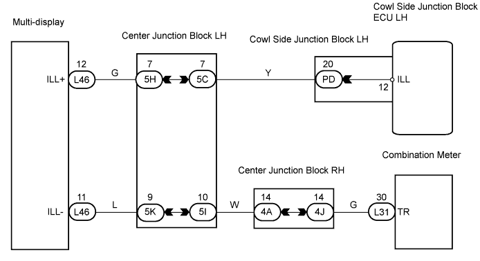
| 1.CHECK COWL SIDE JUNCTION BLOCK LH |
 |
Measure the voltage of the connector.
| Tester Connection | Condition | Specified Condition |
| PD-20 (ILL) - Body ground | Light control switch ON | 10 to 14 V |
|
| ||||
| OK | |
| 2.CHECK MULTI-DISPLAY |
 |
Disconnect the L46 multi-display connector.
Measure the voltage of the wire harness side connector.
| Tester Connection | Condition | Specified Condition |
| L46-12 (ILL+) - Body ground | Light control switch ON | 10 to 14 V |
|
| ||||
| OK | |
| 3.CHECK WIRE HARNESS (MULTI-DISPLAY - COMBINATION METER) |
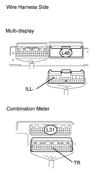 |
Disconnect the L46 multi-display connector.
Disconnect the L31 meter connector.
Measure the resistance of the wire harness side connectors.
| Tester Connection | Condition | Specified Condition |
| L46-11 (ILL-) - L31-30 (TR) | Always | Below 1 Ω |
| L46-11 (ILL-) - Body ground | Always | 10 kΩ or higher |
|
| ||||
| OK | |
| 4.REPLACE COMBINATION METER |
Replace the combination meter with a normal one and check if the same problem occurs again.
|
| ||||
| OK | ||
| ||
