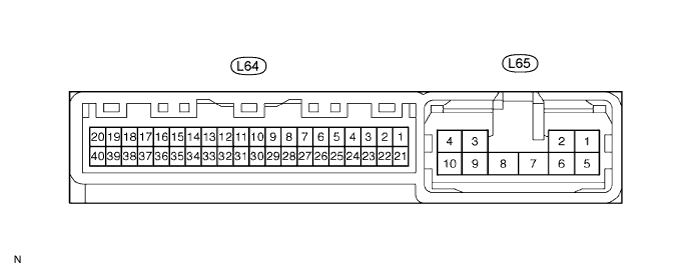
REAR VIEW MONITOR SYSTEM > TERMINALS OF ECU |
| CHECK TELEVISION CAMERA |

| Symbols (Terminal No.) | Wiring Color | Terminal Description | Condition | Specified Condition |
| CV- (a8-1) - CGND (a8-3) | Shielded - W | Display signal (-) | Always | Below 1 Ω |
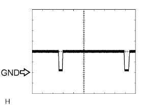
| CV+ (a8-2) - CGND (a8-3) | R - W | Display signal (+) | Engine switch on (IG), shift lever in R position | Pulse generation (see waveform 1) |
| CGND (a8-3) - Body ground | W - Body ground | Power ground | Always | Below 1 Ω |
| CB+ (a8-4) - CGND (a8-3) | B - W | Power ground | Engine switch on (IG), shift lever in R position | Approx. 6 V |
 |
Reference:
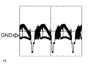
Waveform 1
| Item | Content |
| Symbols (Terminal No.) | CV+ (a8-2) - CV- (a8-1) |
| Tool Setting | 0.2 V/DIV., 0.2 μsec./DIV. |
| Condition | Engine switch on (IG) Shift lever in R position |
| CHECK TELEVISION CAMERA ECU |
| Symbols (Terminal No.) | Wiring Color | Terminal Description | Condition | Specified Condition |
| +B (L65-1) - GND1 (L65-8) | L - W-B | Battery supply | Always | 10 to 14 V |
| IG (L65-2) - GND1 (L65-8) | B - W-B | Engine switch on (IG) signal input | Engine switch on (IG) | 10 to 14 V |
| ACC (L65-5) - GND1 (L65-8) | SB - W-B | Engine switch on (ACC) signal input | Engine switch on (IG or ACC) | 10 to 14 V |
| GND1 (L65-8) - Body ground | W-B - Body ground | Power ground | Always | Below 1 Ω |
| CANL (L64-7) - CANH (L64-8) | W - R | CAN communication | Engine switch off | 54 to 67 Ω |
| VG (L64-9) - GND1 (L65-8) | Shielded - W-B | Display signal output ground (Shielded) | Always | Below 1 Ω |
| R (L64-10) - GND1 (L65-8) | B - W-B | Display signal output (Red) | Map or back monitor is displayed | Pulse generation (see waveform 2) |
| G (L64-11) - GND1 (L65-8) | W - W-B | Display signal output (Green) | Map or back monitor is displayed | Pulse generation (see waveform 2) |
| B (L64-12) - GND1 (L65-8) | Y - W-B | Display signal output (Blue) | Map or back monitor is displayed | Pulse generation (see waveform 2) |
| CGND (L64-19) - GND1 (L65-8) | W - W-B | Television camera ground | Always | Below 1 Ω |
| CB+ (L64-20) - GND1 (L65-8) | B - W-B | Power source to television camera | Engine switch on (IG), shift lever in R position | Approx. 6 V |
| TX+ (L64-29) - GND1 (L65-8) | P - W-B | AVC-LAN control bus | Engine switch on (ACC) | 2 to 3 V |
| TX- (L64-30) - GND1 (L65-8) | V - W-B | AVC-LAN control bus | Engine switch on (ACC) | 2 to 3 V |
| SYNC (L64-31) - GND1 (L65-8) | G - W-B | Synchronized signal output | Map or back monitor is displayed | Pulse generation (see waveform 3) |
| VR (L64-32) - GND1 (L65-8) | R - W-B | Display signal output ground | Always | Below 1 Ω |
| CV- (L64-39) - GND1 (L65-8) | Shielded - W-B | Television camera ground (Shielded) | Always | Below 1 Ω |
| CV+ (L64-40) - GND1 (L65-8) | R - W-B | Display signal of television camera input | Engine switch on (IG), shift lever in R position | Pulse generation (see waveform 1) |
|
Reference:
Waveform 1
| Item | Content |
| Symbols (Terminal No.) | CV+ (L64-40) - GND1 (L65-8) |
| Tool Setting | 0.2 V/DIV., 0.2 μsec./DIV. |
| Condition | Engine switch on (IG) Shift lever in R position |
 |
Waveform 2
| Item | Content |
| Symbols (Terminal No.) | R (L64-10) - GND1 (L65-8) G (L64-11) - GND1 (L65-8) B (L64-12) - GND1 (L65-8) |
| Tool Setting | 200 mV/DIV., 10 μsec./DIV. |
| Condition | Image is displayed (Rear view monitor or navigation system) |
 |
Waveform 3
| Item | Content |
| Symbols (Terminal No.) | SYNC (L64-31) - GND1 (L65-8) |
| Tool Setting | 500 mV/DIV., 10 μsec./DIV. |
| Condition | Image is displayed (Rear view monitor or navigation system) |
