DTC 5C-40 Camera Picture Error |
| DTC No. | DTC Detection Condition | Trouble Area |
| 5C - 40 | Synchronous signal from camera cannot be transmitted |
|
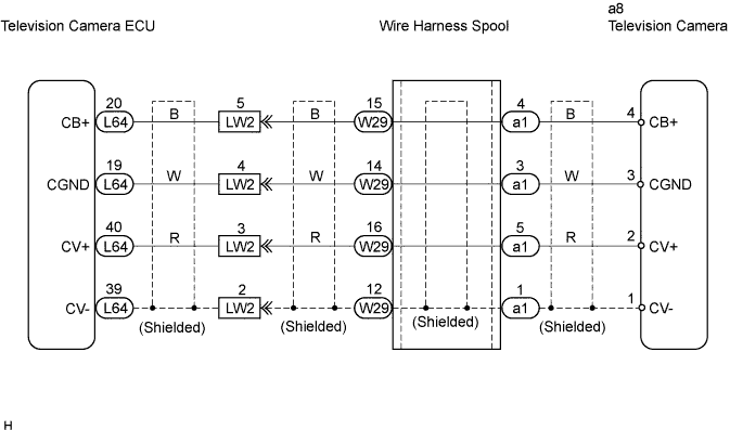
| 1.CHECK WIRE HARNESS (TELEVISION CAMERA ECU - TELEVISION CAMERA) |
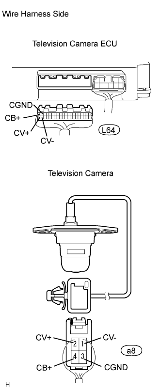 |
Disconnect the L64 ECU connector.
Disconnect the a8 camera connector.
Measure the resistance of the wire harness side connectors.
| Tester Connection | Condition | Specified Condition |
| L64-20 (CB+) - a8-4 (CB+) | Always | Below 1 Ω |
| L64-19 (CGND) - a8-3 (CGND) | Always | Below 1 Ω |
| L64-40 (CV+) - a8-2 (CV+) | Always | Below 1 Ω |
| L64-39 (CV-) - a8-1 (CV-) | Always | Below 1 Ω |
| L64-20 (CB+) - Body ground | Always | 10 kΩ or higher |
| L64-19 (CGND) - Body ground | Always | 10 kΩ or higher |
| L64-39 (CV+) - Body ground | Always | 10 kΩ or higher |
| L64-39 (CV-) - Body ground | Always | 10 kΩ or higher |
|
| ||||
| OK | |
| 2.CHECK TELEVISION CAMERA (POWER SOURCE VOLTAGE) |
 |
Measure the voltage of the connector.
| Tester Connection | Condition | Specified Condition |
| a8-4 (CB+) - a8-3 (CGND) | Engine switch on (IG), shift lever in R position | Approx. 6 V |
|
| ||||
| OK | ||
| ||
