FUEL PRESSURE PULSATION DAMPER > INSTALLATION |
| 1. INSTALL FUEL PRESSURE PULSATION DAMPER |
 |
Apply a light coat of gasoline to a new O-ring and install it to the fuel pressure pulsation damper.
Install the fuel pressure pulsation damper to the fuel delivery pipe.
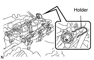
Install the holder.
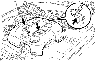
| 2. INSTALL INTAKE AIR SURGE TANK |
 |
Install a new gasket to the intake air surge tank.
Install the intake air surge tank with the 2 nuts.
Using a 5 mm hexagon socket wrench, install the 4 bolts.
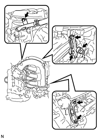 |
Install the 2 surge tank stays with the 4 bolts.
For Chinese specification:
Connect the water hose joint with the bolt.
For except Chinese specification:
Connect the water by-pass pipe with the bolt.
Install the 3 wire harness clamps.
Connect the IACV connector.
Connect the throttle motor connector.
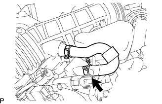
| 3. CONNECT VENTILATION HOSE |
 |
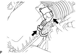
Connect the ventilation hose to the ventilation valve.
| 4. CONNECT UNION TO CHECK VALVE HOSE |
Connect the hose to the surge tank.
| 5. CONNECT WATER BY-PASS HOSE |
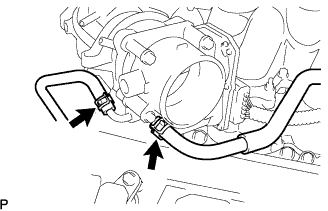 |
Connect the 2 water by-pass hoses to the throttle body.
| 6. INSTALL AIR CLEANER CAP WITH AIR CLEANER HOSE |
 |
Install the air cleaner cap with air cleaner hose with the 4 clamps and hose clamp.
 |
Install the VSV (for EVAP) to the air cleaner hose.
 |
Connect the MAF meter connector and clamp to the air cleaner.
| 7. CONNECT NO. 2 VENTILATION HOSE |
 |
Connect the ventilation hose to the cylinder head cover with the clamp.
| 8. CONNECT CABLE TO BATTERY NEGATIVE TERMINAL |
| 9. ADD ENGINE COOLANT |
| 10. CHECK FOR COOLANT LEAKAGE |
| 11. CHECK FOR FUEL LEAKAGE |
Start the engine, and check that there are no fuel leaks after performing maintenance anywhere on the system.
| 12. CHECK FOR ENGINE OIL LEAKAGE |
Start the engine, and check that there are no oil leaks after performing maintenance.
| 13. INSTALL V-BANK COVER |
 |
Install the V-bank cover with the 2 nuts.
| 14. INSTALL ENGINE ROOM SIDE COVER RH |
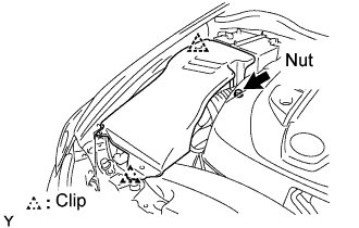 |
Install the side cover with the 2 clips and nut.
| 15. INSTALL COOL AIR INTAKE DUCT SEAL |
 |
Install the intake duct seal with the 7 clips.
| 16. INSTALL ENGINE UNDER COVER |
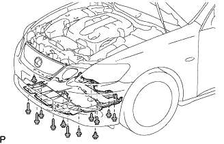 |
Install the under cover with the 10 bolts and 3 clips.
| 17. PERFORM INITIALIZATION |
Perform initialization (Click here).
| 18. WARM UP ENGINE |
After the engine is warmed up, check that the maintained parts operate normally.
