FUEL INJECTOR > INSTALLATION |
| 1. INSTALL FUEL INJECTOR SEAL |
 |
Apply engine conditioner to the injector area shown in the illustration. Using a cloth, clean carbon deposits from the injector and its grooves.
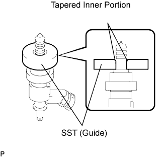 |
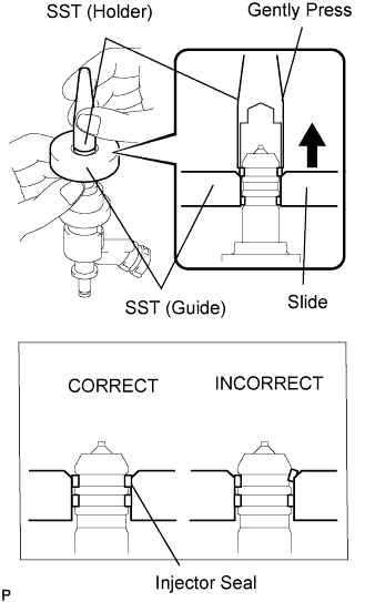
Apply engine oil to the injector contact surface of SST (guide). Then attach SST (guide) to the injector with the tapered inner portion facing the tip of the injector, as shown in the illustration.
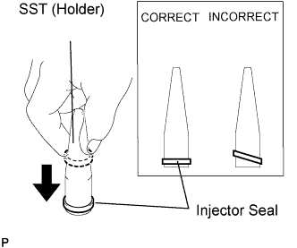 |
Install a new injector seal to SST (holder).
 |
Install SST (holder with injector seal) to the tip of the injector. Using your fingers, slide the seal downward into the injector groove (injector connector side), as shown in the illustration.
 |
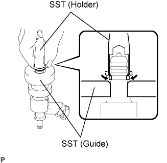
Using SST (holder), gently press downward on the injector seal (injector connector side). Then slowly slide SST (guide) towards the injector tip to settle the seal into the injector groove.
|
Install a new injector seal to the injector groove (injector tip side) as shown in the illustration.
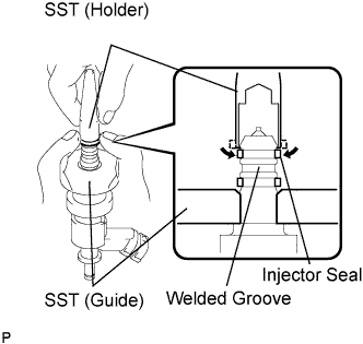 |
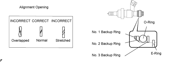
Check that the seal covers the circumference of the injector groove as shown in the illustration.
 |
Slowly slide SST (guide) towards the tip of the injector. When the injector contact surface of SST (guide) aligns with the seal (injector connector side) as shown in the illustration, hold the position for 5 seconds or more to fully align the seal into the injector groove.
 |
Using SST (holder), gently press downward on the injector seal (injector tip side). Then slowly slide SST (guide) towards the injector tip to settle the seal into the injector groove.
 |
Slowly slide SST (guide) towards the tip of the injector. When the injector contact surface of SST (guide) aligns with the seal (injector tip side) as shown in the illustration, hold the position for 5 seconds or more to fully align the seal into the injector groove.
 |
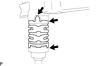
After installing the seals, check that the seal is not scratched, deformed or protruding from the injector groove.
| 2. INSTALL FUEL INJECTOR |
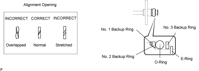
Install a new O-ring, new backup rings (No. 1, No. 2, No. 3) and new E-ring to the fuel injector as shown in the illustration.
Install the injector nozzle holder clamp.
 |
Apply gasoline to the O-ring. Install the nozzle holder clamp by aligning the protruding part of the clamp to the notch of the delivery pipe.
| 3. INSTALL NO. 1 FUEL DELIVERY PIPE |
Install a new injector vibration insulator to the cylinder head.
Apply lubricant to the installation hole of the injector.
 |
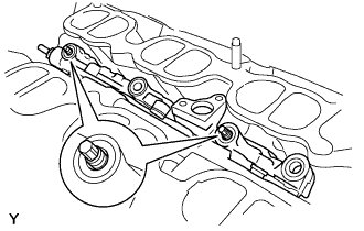
Insert the stud bolt into the fuel delivery pipe until the screw threads protrude enough so that a nut can be attached.
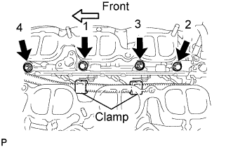 |
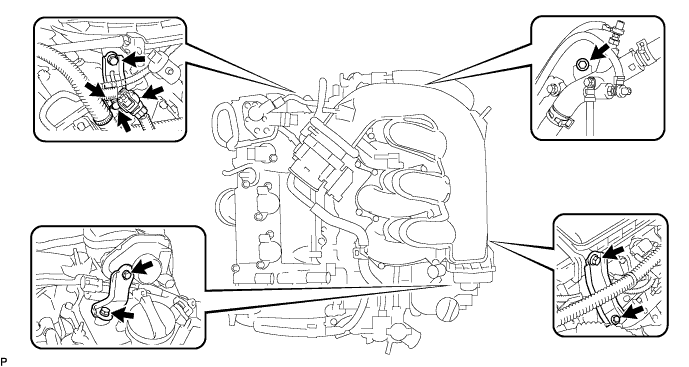
Install the fuel delivery pipe by uniformly tightening the 2 bolts and 2 nuts in several passes in the order shown in the illustration.
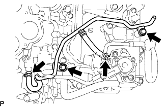
Connect the 3 connectors and 2 clamps.
| 4. INSTALL NO. 2 FUEL DELIVERY PIPE |
Install a new injector vibration insulator to the cylinder head.
Apply lubricant to the installation hole of the injector.
 |
Insert the stud bolt into the No. 2 fuel delivery pipe until the screw threads protrude enough so that a nut can be attached.
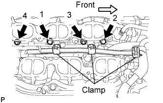 |
Install the fuel delivery pipe by uniformly tightening the 2 bolts and 2 nuts in several passes in the order shown in the illustration.
Connect the 3 connectors and 3 clamps.
| 5. INSTALL NO. 3 FUEL PIPE |
Install a new O-ring, new backup rings (No. 1, No. 2) and new E-ring to the fuel injector as shown in the illustration.
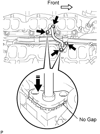 |
Apply gasoline to the O-ring.
Using your hand, press the fuel pipe and delivery pipe together until there is no gap between them. Then install the No. 3 fuel pipe with the 4 bolts.
| 6. CONNECT NO. 2 FUEL PIPE |
Install a new O-ring, new backup rings (No. 1 and No. 2) and new E-ring to the fuel injector as shown in the illustration.
Apply gasoline to the O-ring and connect the fuel pipe to the delivery pipe.
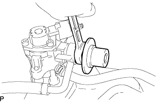
| 7. INSTALL HIGH PRESSURE SIDE FUEL PUMP |
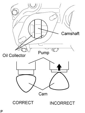 |
Turn the crankshaft until the flat of the cam is facing the cylinder head cover's fuel pump attachment hole, as shown in the illustration.
Pour 30 cc of engine oil through the cylinder head cover's fuel pump attachment hole into the cylinder head oil collector.
 |
Apply a coat of engine oil to the pump activation cam and pump lifter part.
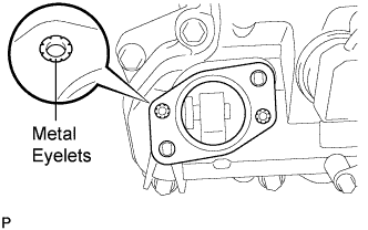 |
Install a new fuel pump insulator to the cylinder head cover. Then pass the 2 stud bolts through the holes of the fuel pump and set it on the insulator.
Install the union nut of the No. 1 fuel pipe without damaging its seal surface. Tighten the nut as much as possible by hand.
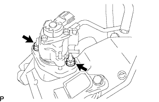 |
Install the 2 nuts and tighten them in several passes.
Connect the fuel hose.
| 8. INSTALL NO. 2 FUEL PIPE |
 |
Install the fuel pipe to the delivery pipe with the 2 bolts.
| 9. INSTALL NO. 1 FUEL PIPE |
 |
Install the No.1 fuel pipe with the 2 bolts.
Connect the fuel pipe hose.
| 10. INSTALL FUEL PRESSURE PULSATION DAMPER |
 |
Install a new gasket and the fuel pulsation damper to the fuel pump.
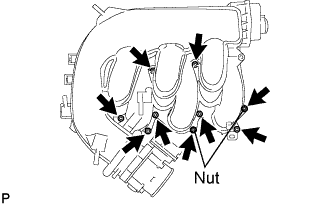
| 11. INSTALL INTAKE MANIFOLD |
 |
Install a new gasket and the intake manifold with the 4 bolts and 4 nuts.
Connect the DC motor connector for the SCV.
Connect the SCV position sensor connector.
| 12. INSTALL INTAKE AIR SURGE TANK |
 |
Install a new gasket to the intake air surge tank.
Install the intake air surge tank with the 2 nuts.
Using a 5 mm hexagon socket wrench, install the 7 bolts.
Install the 2 surge tank stays with the 4 bolts.
Connect the 2 wire harness clamps.
Connect the water hose joint with the bolt.
Install the intake manifold stay with the 2 bolts.
Connect the wire harness clamp to the intake air surge tank.
Connect the IACV connector.
Connect the SCV position sensor connector.
Connect the throttle motor connector.
| 13. CONNECT FUEL MAIN TUBE |
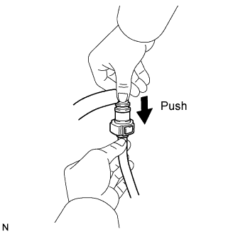 |
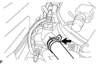
Connect the connector to the fuel main pipe. Push the two parts together firmly until a "click" sound is heard. Then attach the lock claws to the connector by pushing down on the connector cover.
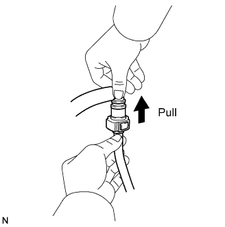 |
Check that the connector and fuel main pipe are securely connected by trying to pull them apart.
 |
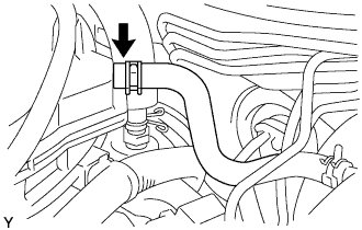
Install the fuel pipe clamp.
| 14. CONNECT VENTILATION HOSE |
 |
Connect the ventilation hose to the ventilation valve.
| 15. CONNECT UNION TO CHECK VALVE HOSE |
 |
Connect the hose to the surge tank.
| 16. INSTALL ENGINE REAR COVER |
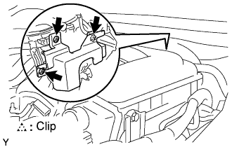 |
Install the engine rear cover with the 3 clips.
| 17. CONNECT HEATER WATER INLET HOSE |
 |
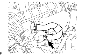
Connect the hose to the pipe.
| 18. CONNECT WATER BY-PASS HOSE |
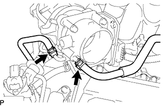 |
Connect the 2 water by-pass hoses to the throttle body.
| 19. INSTALL AIR CLEANER CAP WITH AIR CLEANER HOSE |
 |
Install the air cleaner cap with air cleaner hose assembly with the 4 clamps and hose clamp.
 |
Install the VSV (for EVAP )to the air cleaner hose.
 |
Connect the MAF meter connector and clamp to the air cleaner.
| 20. CONNECT NO. 2 VENTILATION HOSE |
 |
Connect the ventilation hose to the cylinder head cover with the clamp.
| 21. CONNECT CABLE TO NEGATIVE BATTERY TERMINAL |
| 22. ADD ENGINE COOLANT |
Tighten all the plugs and fill the radiator with TOYOTA Super Long Life Coolant (SLLC).
Add engine coolant.
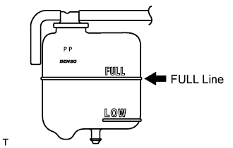
Slowly pour coolant into the radiator reservoir until it reaches the FULL line.
Press the inlet and outlet radiator hoses several times by hand, and then check the level of the coolant.
If the coolant level is low, add coolant.
Install the radiator cap and reservoir cap.
Bleed air from the cooling system.
Warm up the engine until the thermostat opens. While the thermostat is open, circulate the coolant for several minutes.
Maintain the engine speed at 2,000 to 2,500 rpm.
Press the inlet and outlet radiator hoses several times by hand to bleed air.
Stop the engine, and wait until the engine coolant cools down to ambient temperature.
 |
Check the coolant level in the radiator reservoir.
If the coolant level is low, add SLLC to the radiator reservoir FULL line.
| 23. CHECK FOR COOLANT LEAKAGE |
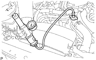 |
Fill the radiator with coolant and attach a radiator cap tester.
Warm up the engine.
Using a radiator cap tester, increase the pressure inside the radiator to 118 kPa (1.2 kgf/cm, 17 psi), and check that the pressure does not drop.
If the pressure drops, check the hoses, radiator and water pump for leaks. If no external leaks are found, check the heater core, cylinder block and head.
| 24. CHECK FOR FUEL LEAKAGE |
Start the engine, and check that there are no fuel leaks after performing maintenance anywhere on the system.
| 25. CHECK FOR ENGINE OIL LEAKAGE |
Start the engine, and check that there are no oil leaks after performing maintenance.
| 26. INSTALL V-BANK COVER |
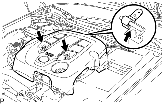 |
Install the V-bank cover with the 2 nuts.
| 27. INSTALL ENGINE ROOM SIDE COVER RH |
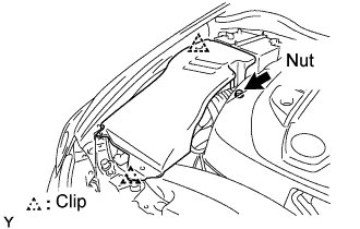 |
Install the side cover with the 2 clips and nut.
| 28. INSTALL COOL AIR INTAKE DUCT SEAL |
 |
Install the intake duct seal with the 7 clips.
| 29. INSTALL ENGINE UNDER COVER |
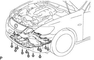 |
Install the under cover with the 10 bolts and 3 clips.
| 30. PERFORM INITIALIZATION |
Perform initialization (Click here).
| 31. WARM UP ENGINE |
After the engine is warmed up, check that the maintained parts operate normally.
