POWER MIRROR CONTROL SYSTEM > TERMINALS OF ECU |
| CHECK FRONT MULTIPLEX NETWORK DOOR ECU LH |

Disconnect the O3, O4 and i1 ECU connectors.
Measure the voltage and resistance of the wire harness side connectors.
| Symbols (Terminal No.) | Wiring Color | Terminal Description | Condition | Specified Condition |
| GND (O3-1) - Body ground | W-B - Body ground | Ground | Always | Below 1 Ω |
| CPUB (O3-4) - GND (O3-1) | L-G - W-B | Battery (ECU power source) | Always | 10 to 14 V |
| SIG (O3-3) - GND (O3-1) | Y - W-B | Ignition power supply | Engine switch off | Below 1 V |
| SIG (O3-3) - GND (O3-1) | Y - W-B | Ignition power supply | Engine switch on (IG) | 10 to 14 V |
| BDR (O3-6) - GND (O3-1) | L - W-B | Battery (ECU power source) | Always | 10 to 14 V |
| - (i1-12) - + (i1-4) | B-R - BR-W | Mirror heater output and ground | 25°C (75°F) | 3.6 to 4.8 Ω |
| *SEL1 (O4-11) - SELE (O4-12) | P - P | Terminal for identification of driver side | Always | Below 1 Ω |
Reconnect the O3, O4 and i1 ECU connectors.
Measure the voltage of the connectors.
| Symbols (Terminal No.) | Wiring Color | Terminal Description | Condition | Specified Condition |
| MR (i1-3) - GND (O3-1) | G - W-B | Mirror retract motor output (retracting) | Mirror retract switch ON (Outer rear view mirror LH is retracting) | 10 to 14 V |
| MF (i1-11) - GND (O3-1) | L - W-B | Mirror retract motor output (returning) | Mirror retract switch OFF (Outer rear view mirror LH is returning) | 10 to 14 V |
| M+ (i1-10) - GND (O3-1) | B - W-B | Mirror motor output | Mirror master switch LEFT, Mirror control switch OFF | Below 1 V |
| M+ (i1-10) - GND (O3-1) | B - W-B | Mirror motor output | Mirror master switch LEFT, Mirror control switch UP or LEFT | Below 1 V |
| M+ (i1-10) - GND (O3-1) | B - W-B | Mirror motor output | Mirror master switch LEFT, Mirror control switch DOWN or RIGHT | 10 to 14 V |
| MH (i1-9) - GND (O3-1) | R - W-B | Mirror motor output | Mirror master switch LEFT, Mirror control switch OFF | Below 1 V |
| MH (i1-9) - GND (O3-1) | R - W-B | Mirror motor output | Mirror master switch LEFT, Mirror control switch RIGHT | Below 1 V |
| MH (i1-9) - GND (O3-1) | R - W-B | Mirror motor output | Mirror master switch LEFT, Mirror control switch LEFT | 10 to 14 V |
| MV (i1-1) - GND (O3-1) | W - W-B | Mirror motor output | Mirror master switch LEFT, Mirror control switch OFF | Below 1 V |
| MV (i1-1) - GND (O3-1) | W - W-B | Mirror motor output | Mirror master switch LEFT, Mirror control switch DOWN | Below 1 V |
| MV (i1-1) - GND (O3-1) | W - W-B | Mirror motor output | Mirror master switch LEFT, Mirror control switch UP | 10 to 14 V |
| + (i1-4) - GND (O3-1) | BR-W - W-B | Mirror heater output | Rear defogger switch ON | 10 to 14 V |
| + (i1-4) - GND (O3-1) | BR-W - W-B | Mirror heater output | Rear defogger switch OFF | Below 1 V |
| VSSL (i1-6) - E1 (i1-14) | V - GR | Vertical direction position signal | Mirror master switch RIGHT or LEFT, Mirror control switch UP or DOWN | Voltage fluctuates between 0 and 5 V |
| HSSL (i1-13) - E1 (i1-14) | LG - GR | Horizontal direction position signal | Mirror master switch RIGHT or LEFT, Mirror control switch RIGHT or LEFT | Voltage fluctuates between 0 and 5 V |
| VC (i1-5) - E1 (i1-14) | SB - GR | Power source for mirror position sensor | Engine switch off during sleep mode | Below 1 V |
| VC (i1-5) - E1 (i1-14) | SB - GR | Power source for mirror position sensor | Engine switch on (IG) | 3.5 to 5.5 V |
| ECI+ (O3-18) - ECI- (O3-19) | BR - O | EC mirror signal | Electrochromic mirror system is operating | 1.05 to 1.35 V |
| ECI+ (O3-18) - ECI- (O3-19) | BR - O | EC mirror signal | Electrochromic mirror system is not operating | Below 1 V |
| EC+ (i1-7) - EC- (i1-15) | BR - B-L | EC mirror signal | Electrochromic mirror system is operating | 1.05 to 1.35 V |
| EC+ (i1-7) - EC- (i1-15) | BR - B-L | EC mirror signal | Electrochromic mirror system is not operating | Below 1 V |
| *SEL1 (O4-11) - GND (O3-1) | P - W-B | Terminal for identification of driver side | Always | Below 1 V |
| CHECK FRONT MULTIPLEX NETWORK DOOR ECU RH |

Disconnect the N3, N4 and j1 ECU connectors.
Measure the voltage and resistance of the wire harness side connectors.
| Symbols (Terminal No.) | Wiring Color | Terminal Description | Condition | Specified Condition |
| GND (N4-1) - Body ground | W-B - Body ground | Ground | Always | Below 1 Ω |
| CPUB (N4-4) - GND (N4-1) | LG - W-B | Battery (ECU power source) | Always | 10 to 14 V |
| SIG (N4-3 - GND (N4-1) | L - W-B | Ignition power supply | Engine switch off | Below 1 V |
| SIG (N4-3) - GND (N4-1) | L - W-B | Ignition power supply | Engine switch on (IG) | 10 to 14 V |
| BDR (N4-6) - GND (N4-1) | L - W-B | Battery (ECU power source) | Always | 10 to 14 V |
| - (j1-12) - + (j1-4) | B-R - BR-W | Mirror heater output and ground | 25°C (75°F) | 3.6 to 4.8 Ω |
| *SEL1 (N3-11) - SELE (N3-12) | P - P | Terminal for identification of driver side | Always | Below 1 Ω |
Reconnect the N3, N4 and j1 ECU connectors.
Measure the voltage of the connectors.
| Symbols (Terminal No.) | Wiring Color | Terminal Description | Condition | Specified Condition |
| MR (j1-3) - GND (N4-1) | G - W-B | Mirror retract motor output (retracting) | Mirror retract switch ON (Outer rear view mirror RH is retracting) | 10 to 14 V |
| MF (j1-11) - GND (N4-1) | L - W-B | Mirror retract motor output (returning) | Mirror retract switch OFF (Outer rear view mirror RH is returning) | 10 to 14 V |
| M+ (j1-10) - GND (N4-1) | B - W-B | Mirror motor output | Mirror master switch RIGHT, Mirror control switch OFF | Below 1 V |
| M+ (j1-10) - GND (N4-1) | B - W-B | Mirror motor output | Mirror master switch RIGHT, Mirror control switch UP or LEFT | Below 1 V |
| M+ (j1-10) - GND (N4-1) | B - W-B | Mirror motor output | Mirror master switch RIGHT, Mirror control switch DOWN or RIGHT | 10 to 14 V |
| MH (j1-9) - GND (N4-1) | R - W-B | Mirror motor output | Mirror master switch RIGHT, Mirror control switch OFF | Below 1 V |
| MH (j1-9) - GND (N4-1) | R - W-B | Mirror motor output | Mirror master switch RIGHT, Mirror control switch RIGHT | Below 1 V |
| MH (j1-9) - GND (N4-1) | R - W-B | Mirror motor output | Mirror master switch RIGHT, Mirror control switch LEFT | 10 to 14 V |
| MV (j1-1) - GND (N4-1) | W - W-B | Mirror motor output | Mirror master switch RIGHT, Mirror control switch OFF | Below 1 V |
| MV (j1-1) - GND (N4-1) | W - W-B | Mirror motor output | Mirror master switch RIGHT, Mirror control switch DOWN | Below 1 V |
| MV (j1-1) - GND (N4-1) | W - W-B | Mirror motor output | Mirror master switch RIGHT, Mirror control switch UP | 10 to 14 V |
| + (j1-4) - GND (N4-1) | BR-W - W-B | Mirror heater output | Rear defogger switch ON | 10 to 14 V |
| + (j1-4) - GND (N4-1) | BR-W - W-B | Mirror heater output | Rear defogger switch OFF | Below 1 V |
| VSSR (j1-6) - E1 (j1-14) | V - GR | Vertical direction position signal | Mirror master switch RIGHT or LEFT, Mirror control switch UP or DOWN | Voltage fluctuates between 0 and 5 V |
| HSSR (j1-13) - E1 (j1-14) | LG - GR | Horizontal direction position signal | Mirror master switch RIGHT or LEFT, Mirror control switch RIGHT or LEFT | Voltage fluctuates between 0 and 5 V |
| VC (j1-5) - E1 (j1-14) | SB - GR | Power source for mirror position sensor | Engine switch off during sleep mode | Below 1 V |
| VC (j1-5) - E1 (j1-14) | SB - GR | Power source for mirror position sensor | Engine switch on (IG) | 3.5 to 5.5 V |
| ECI+ (N4-18) - ECI- (N4-19) | BR - O | EC mirror signal | Electrochromic mirror system is operating | 1.05 to 1.35 V |
| ECI+ (N4-18) - ECI- (N4-19) | BR - O | EC mirror signal | Electrochromic mirror system is not operating | Below 1 V |
| EC+ (j1-7) - EC- (j1-15) | BR - B-L | EC mirror signal | Electrochromic mirror system is operating | 1.05 to 1.35 V |
| EC+ (j1-7) - EC- (j1-15) | BR - B-L | EC mirror signal | Electrochromic mirror system is not operating | Below 1 V |
| *SEL1 (N3-11) - GND (N4-1) | P - W-B | Terminal for identification of driver side | Always | Below 1 V |
| INSPECT MULTIPLEX NETWORK MASTER SWITCH ASSEMBLY |
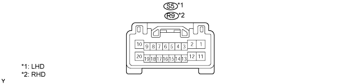
Disconnect the S5 or R9 master switch connector.
Measure the voltage and resistance of the wire harness side connector.
| Symbols (Terminal No.) | Wiring Color | Terminal Description | Condition | Specified Condition |
| E (S5-2) - Body ground | W-B - Body ground | Ground | Always | Below 1 Ω |
| BDR1 (S5-10) - E (S5-2) | Y - W-B | Power window power source | Always | 10 to 14 V |
| CPUB (S5-9) - E (S5-2) | G - W-B | Power source for CPU and relevant device | Always | 10 to 14 V |
| SIG (S5-20) - E (S5-2) | V - W-B | Power source for CPU and relevant device | Engine switch off | Below 1 V |
| SIG (S5-20) - E (S5-2) | V - W-B | Power source for CPU and relevant device | Engine switch on (IG) | 10 to 14 V |
| Symbols (Terminal No.) | Wiring Color | Terminal Description | Condition | Specified Condition |
| E (R9-2) - Body ground | W-B - Body ground | Ground | Always | Below 1 Ω |
| BDR1 (R9-10) - E (R9-2) | Y - W-B | Power window power source | Always | 10 to 14 V |
| CPUB (R9-9) - E (R9-2) | G - W-B | Power source for CPU and relevant device | Always | 10 to 14 V |
| SIG (R9-20) - E (R9-2) | V - W-B | Power source for CPU and relevant device | Engine switch off | Below 1 V |
| SIG (R9-20) - E (R9-2) | V - W-B | Power source for CPU and relevant device | Engine switch on (IG) | 10 to 14 V |
Reconnect the S5 or R9 master switch connector.
Measure the voltage of the connector.
| Symbols (Terminal No.) | Wiring Color | Terminal Description | Condition | Specified Condition |
| MM (S5-3) - E (S5-2) | SB - W-B | SET switch signal | SET switch OFF | 10 to 14 V |
| MM (S5-3) - E (S5-2) | SB - W-B | SET switch signal | SET switch ON | Below 1 V |
| M1 (S5-13) - E (S5-2) | L - W-B | M1 switch signal | M1 switch OFF | 10 to 14 V |
| M1 (S5-13) - E (S5-2) | L - W-B | M1 switch signal | M1 switch ON | Below 1 V |
| M2 (S5-17) - E (S5-2) | V - W-B | M2 switch signal | M2 switch OFF | 10 to 14 V |
| M2 (S5-17) - E (S5-2) | V - W-B | M2 switch signal | M2 switch ON | Below 1 V |
| M3 (S5-18) - E (S5-2) | R - W-B | M3 switch signal | M3 switch OFF | 10 to 14 V |
| M3 (S5-18) - E (S5-2) | R - W-B | M3 switch signal | M3 switch ON | Below 1 V |
| Symbols (Terminal No.) | Wiring Color | Terminal Description | Condition | Specified Condition |
| MM (R9-3) - E (R9-2) | Y - W-B | SET switch signal | SET switch OFF | 10 to 14 V |
| MM (R9-3) - E (R9-2) | Y - W-B | SET switch signal | SET switch ON | Below 1 V |
| M1 (R9-13) - E (R9-2) | O - W-B | M1 switch signal | M1 switch OFF | 10 to 14 V |
| M1 (R9-13) - E (R9-2) | O - W-B | M1 switch signal | M1 switch ON | Below 1 V |
| M2 (R9-17) - E (R9-2) | LG - W-B | M2 switch signal | M2 switch OFF | 10 to 14 V |
| M2 (R9-17) - E (R9-2) | LG - W-B | M2 switch signal | M2 switch ON | Below 1 V |
| M3 (R9-18) - E (R9-2) | SB - W-B | M3 switch signal | M3 switch OFF | 10 to 14 V |
| M3 (R9-18) - E (R9-2) | SB - W-B | M3 switch signal | M3 switch ON | Below 1 V |
