AIR FUEL RATIO SENSOR (for Sensor 1) > ON-VEHICLE INSPECTION |
| 1. INSPECT AIR FUEL RATIO SENSOR |
Disconnect the A/F sensor connector.
 |
Measure the heater resistance between terminals 1 (HT) and 2 (+B) of the sensor.
| 2. INSPECT AIR-FUEL RATIO COMPENSATION SYSTEM |
Measure the voltage between the terminals of the ECM connectors.
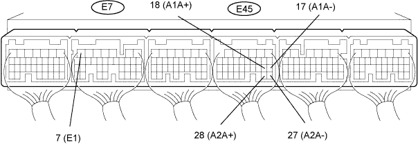
| Tester Connection | Condition | Specified Condition |
| E45-18 (A1A+) - E7-7 (E1) | Engine switch on (IG) | 3.3 V |
| E45-17 (A1A-) - E7-7 (E1) | Engine switch on (IG) | 2.9 V |
| E45-28 (A2A+) - E7-7 (E1) | Engine switch on (IG) | 3.3 V |
| E45-27 (A2A-) - E7-7 (E1) | Engine switch on (IG) | 2.9 V |
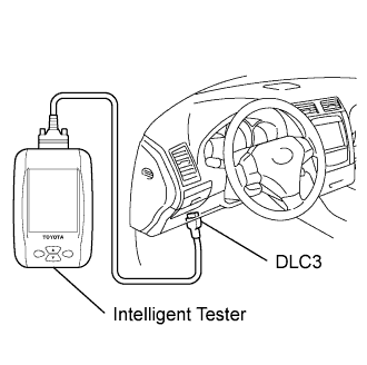 |
Connect the intelligent tester to the DLC3.
Turn the engine switch on (IG).
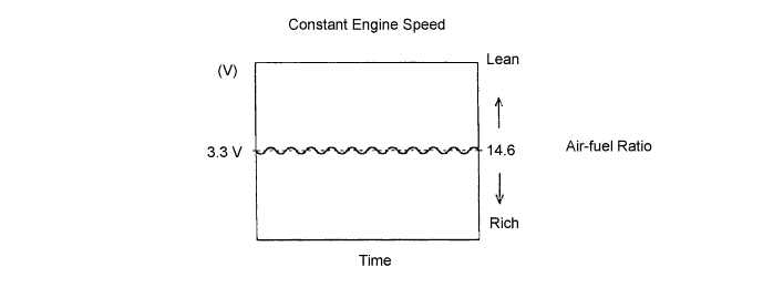
Select the following menus: Powertrain / Engine / Data List / A/FS B1 S1, A/FS B2 S1, O2S B1 S2 and O2S B2 S2.
Warm up the A/F sensor by running the engine at 2, 500 rpm for approximately 2 minutes.
Keep the engine speed at 2,500 rpm and confirm that the displays of "A/FS B1 S1" and "A/FS B2 S1" are as shown in the illustration.
Check the displays of "O2S B1 S2" and "O2S B2 S2" with the engine speed at 2,500 rpm.
