FUEL INJECTOR > INSTALLATION |
| 1. INSTALL FUEL INJECTOR ASSEMBLY |
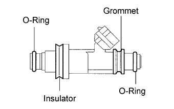 |
Install a new O-ring, grommet and insulator to the injector.
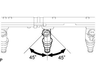 |
Push and rotate the injector 45° clockwise and counterclockwise to install it to the delivery pipe.
Check that the injector rotates smoothly.
| 2. INSTALL NO. 2 FUEL DELIVERY PIPE SUB-ASSEMBLY |
 |
Install the delivery pipe (with injector) to the intake manifold.
 |
With the condition as stated above, rotate the injector 45° clockwise and counterclockwise.
With the spacer contacting the delivery pipe, install the delivery pipe with the 2 nuts.
| 3. INSTALL FUEL DELIVERY PIPE SUB-ASSEMBLY |
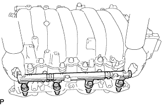 |
Install the delivery pipe (with injector) to the intake manifold.
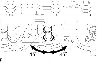 |
With the condition as stated above, rotate the injector 45° clockwise and counterclockwise.
With the spacer contacting the delivery pipe, install the delivery pipe with the 2 nuts.
| 4. INSTALL FUEL PRESSURE PULSATION DAMPER ASSEMBLY |
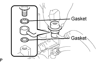 |
Using a wrench, install 4 new gaskets and 2 fuel pulsation dampers to the fuel pipe with the 2 bolts.
| 5. INSTALL INTAKE MANIFOLD |
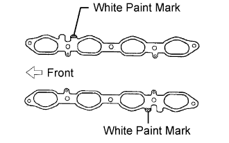 |
Set 2 new gaskets on the cylinder head.
 |
Install the intake manifold to the gasket and cylinder head with the 6 bolts and 4 nuts.
Connect the 8 injector connectors.
| 6. INSTALL NO. 2 FUEL PIPE ASSEMBLY |
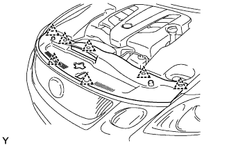
| 7. INSTALL ENGINE WIRE |
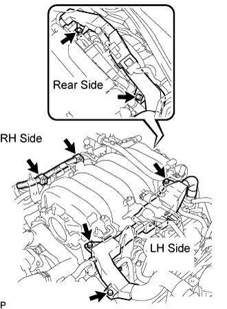 |
Install the wire protector (LH side) with the 3 bolts.
Install the 2 wire clamps on the engine wire (RH side) to the brackets on the RH delivery pipe.
Install the engine wire protector (rear side) to the rear water by-pass joint and RH cylinder head with the 2 bolts.
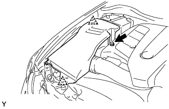
| 8. INSTALL NO. 3 V-BANK COVER BRACKET |
Install the bracket to the manifold with the bolt, as shown in E in the illustration below.
Connect the connector.
| 9. INSTALL NO. 2 V-BANK COVER BRACKET |
Install the bracket to the manifold with the bolt, as shown in D in the illustration below.
| 10. INSTALL NO. 1 VACUUM SWITCHING VALVE ASSEMBLY |
Install the bracket of the VSV to the manifold with the bolt, as shown in C in the illustration below.
Connect the vacuum hose to the VSV, as shown in C in the illustration below.
Connect the connector to the VSV, as shown in C in the illustration below.
| 11. INSTALL NO. 1 V-BANK COVER BRACKET |
Install the bracket to the manifold with the bolt, as shown in B in the illustration below.
| 12. INSTALL NO. 4 V-BANK COVER BRACKET |
Install the bracket to the manifold with the 2 nuts, as shown in A in the illustration below.

| 13. INSTALL THROTTLE BODY ASSEMBLY |
 |
Install a new gasket and the throttle body with the 2 bolts and 2 nuts.
 |
Connect the 2 water by-pass hoses.
Connect the connector and wire.
Connect the PCV hose.
| 14. INSTALL INTAKE AIR CONNECTOR PIPE |
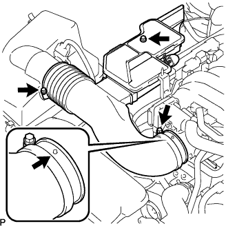 |
Install the connector pipe with the bolt and 2 hose clamps.
Connect the air hose and No. 1 ventilation hose.
| 15. CONNECT CABLE TO NEGATIVE BATTERY TERMINAL |
| 16. CHECK FOR FUEL LEAKS |
Check for fuel leaks (Click here).
| 17. ADD COOLANT |
| 18. CHECK FOR COOLANT LEAKS |
Check for engine coolant leaks (Click here).
| 19. INSTALL V-BANK COVER |
Install the cover with the 2 nuts.
| 20. INSTALL ENGINE ROOM SIDE COVER RH |
 |
Install the side cover with the 2 clips and nut.
| 21. INSTALL ENGINE ROOM SIDE COVER LH |
 |
Install the side cover with the 3 clips.
| 22. INSTALL AIR INTAKE DUCT SEAL |
 |
Install the intake duct seal with the 7 clips.
| 23. PERFORM INITIALIZATION |
Perform initialization (Click here).
