FUEL TANK > INSTALLATION |
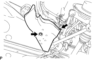
| 1. INSTALL NO. 1 FUEL TANK PROTECTOR SUB-ASSEMBLY |
 |
Install the tank protector with the 2 nuts.
| 2. INSTALL FUEL TANK CUSHION |
 |
Install the tank cushions and tank brackets.
| 3. INSTALL FUEL TANK MAIN TUBE SUB-ASSEMBLY |
 |
Install the fuel tank main tube to the 2 clamps.
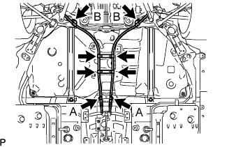
| 4. INSTALL FUEL TANK SUB-ASSEMBLY |
Set a mission jack to the fuel tank and lift it up.
Install the 2 fuel tank bands with the 4 bolts.
Install the 2 nuts.
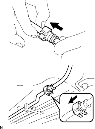
| 5. CONNECT EMISSION HOSE |
 |
Connect the 2 fuel emission hoses.
Install the bracket.
| 6. CONNECT FUEL TANK TO FILLER PIPE HOSE |
 |
Connect the fuel tank to filler pipe hose with the clamp.
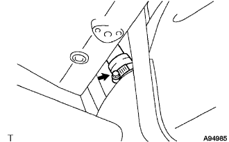
| 7. CONNECT FUEL TANK MAIN TUBE SUB-ASSEMBLY |
 |
Connect the fuel tank main tube connector.
Install the fuel hose connector cover to the pipe.
| 8. CONNECT PARKING BRAKE CABLE ASSEMBLY |
 |
Connect the 4 clamps.
Connect the 2 parking brake cables with the 4 bolts.
| 9. INSTALL REAR FLOOR SIDE MEMBER COVER LH |
 |
Install the side member cover with the 2 bolts.
| 10. INSTALL REAR FLOOR SIDE MEMBER COVER RH |
 |
Install the side member cover with the 2 bolts.
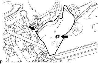
| 11. INSTALL NO. 1 DIFFERENTIAL SUPPORT PROTECTOR |
 |
Install the differential support protector with the 2 nuts.
| 12. INSTALL NO. 2 DIFFERENTIAL SUPPORT PROTECTOR |
Install the differential support protector with the 2 nuts.
| 13. INSTALL NO. 2 FUEL TANK PROTECTOR |
 |
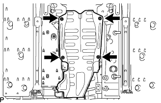
Install the tank protector with the 4 nuts.
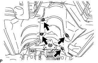
| 14. ADJUST PROPELLER WITH CENTER BEARING SHAFT ASSEMBLY |
 |
Remove the SST from the transmission.
Insert the yoke of the intermediate shaft into the transmission.
 |
Install the 2 center support bearing washers and center support bearing, and temporarily tighten the 2 bolts.
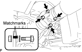 |
Align the matchmarks on the propeller shaft flange and differential companion flange, and connect the shaft with the 4 bolts, washers and nuts.
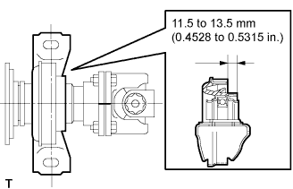 |
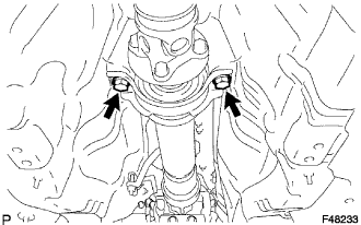
Adjust the dimension between the edge surface of the center support bearing and the edge surface of the cushion to 11.5 to 13.5 mm (0.4528 to 0.5315 in.) respectively as shown in illustration.
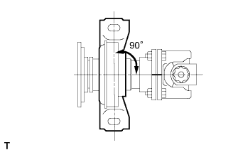 |
Check that the center line of the bracket is at right angles to the shaft axial direction.
|
Tighten the 2 bolts.
| 15. INSTALL FRONT FLOOR NO. 1 HEAT INSULATOR |
 |
Install the heat insulator with the 4 nuts.
| 16. INSTALL FRONT FLOOR COVER CENTER RH |
 |
Install the floor cover center with the 3 nuts.
| 17. INSTALL EXHAUST PIPE ASSEMBLY |
Install the exhaust pipe (Click here).
| 18. INSTALL FUEL RETURN VENT TUBE SUB-ASSEMBLY |
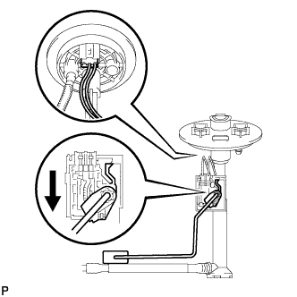 |
Install the fuel sender gauge.
Set the fuel sender gauge to the fuel vent tube. Then slide the sender gauge downward to install it.
Connect the fuel sender gauge connector.
 |
Set the fuel return vent tube to the fuel tank.
Apply a light coat of gasoline to a new gasket, and set it to the fuel tank.
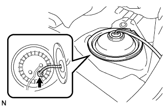
Connect the fuel tube connector, and set the fuel suction with pump and gauge.
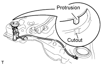
Align the protrusion of the fuel suction tube and the cutout of the fuel tank.
 |
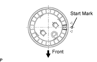
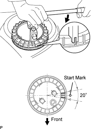
While holding the fuel suction tube by hand, align the start marks of a new fuel pump gauge retainer and the fuel tank. Install the fuel pump retainer to the fuel tank.
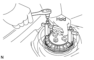 |
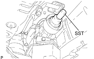
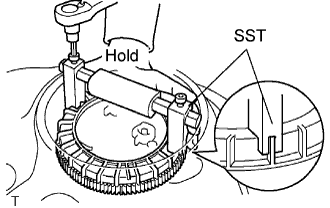
Using a 6 mm socket, set SST to the fuel pump gauge retainer.
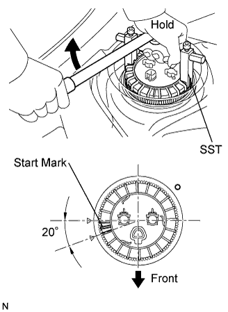 |
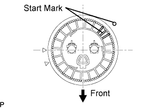
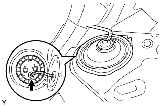
Hold SST with one hand and use SST to tighten the fuel pump gauge retainer 2 turns so that that the start mark on the retainer is within the indicated range in the illustration.
| 19. INSTALL REAR FLOOR SERVICE HOLE COVER |
 |
Connect the fuel sender gauge connector.
Install the service hole cover with new butyl tape.
| 20. INSTALL FUEL SUCTION WITH PUMP AND GAUGE TUBE ASSEMBLY |
Apply a light coat of gasoline to a new gasket, and install it to the fuel tank.
Connect the fuel tube connector, and set the fuel suction with pump and gauge.
 |
Align the protrusion of the fuel suction tube and the cutout of the fuel tank.
 |
While holding the fuel suction tube by hand, align the starting marks of a new fuel pump gauge retainer and the fuel tank. Install the fuel pump retainer to the fuel tank.
 |
Using a 6 mm socket, set SST to the fuel pump gauge retainer.
 |
Hold SST with one hand and use SST to tighten the fuel pump gauge retainer 2 turns so that the start mark on the retainer is within the indicated range in the illustration.
 |
Connect the fuel tank main tube.
Push the fuel tube joint into the plug of the fuel suction plate, then install the 2 tube joint clips.
Connect the fuel suction tube connector.
| 21. INSTALL REAR FLOOR NO. 2 SERVICE HOLE COVER |
 |
Connect the fuel pump connector.
Install the service hole cover with new butyl tape.
| 22. INSTALL ROOM NO. 3 PARTITION PAD |
 |
Install the partition pad with the clip.
| 23. INSTALL REAR SEAT CUSHION ASSEMBLY |
 |
Attach the seat cushion's 2 rear hooks to the seatback.
Attach the seat cushion's 2 front hooks to the vehicle body.
Confirm that the seat cushion is firmly installed.
| 24. CONNECT CABLE TO NEGATIVE BATTERY TERMINAL |
| 25. CHECK FOR FUEL LEAKS |
Start the engine, and check that there are no fuel leaks after performing maintenance anywhere on the system.
| 26. PERFORM INITIALIZATION |
Perform initialization (Click here).
