FUEL TANK > REMOVAL |
| 1. DISCHARGE FUEL SYSTEM PRESSURE |
Disconnect the cable from the negative (-) battery terminal.
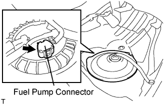 |
Disconnect the fuel pump connector.
Connect the cable to the negative (-) battery terminal.
Start the engine. After the engine has stopped on its own, turn the engine switch off.
Crank the engine again, then check that the engine does not start.
Loosen the fuel tank cap, then discharge the pressure in the fuel tank completely.
Connect the fuel pump connector.
| 2. DISCONNECT CABLE FROM NEGATIVE BATTERY TERMINAL |
| 3. REMOVE REAR SEAT CUSHION ASSEMBLY |
 |
Detach the seat cushion's 2 front hooks from the vehicle body.
Choose a hook to detach first. Place your hands near the hook as shown in the illustration. Then lift the seat cushion to detach the hook.
Repeat for the other hook.
Detach the seat cushion's 2 rear hooks from the seatback.
Remove the seat cushion.
| 4. REMOVE ROOM NO. 3 PARTITION PAD |
 |
Remove the clip and room partition pad.
| 5. REMOVE REAR FLOOR NO. 2 SERVICE HOLE COVER |
 |
Remove the service hole cover and disconnect the fuel pump connector.
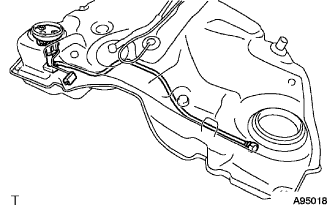
| 6. REMOVE FUEL SUCTION TUBE WITH PUMP AND GAUGE ASSEMBLY |
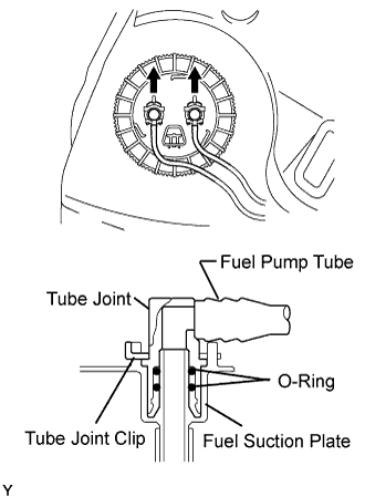
Disconnect the fuel tank main tube and pump tube.
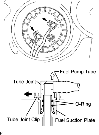 |
Remove the 2 tube joint clips and fuel tubes.
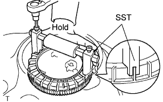 |
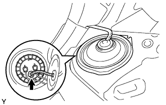
Using a 6 mm socket, set SST to the fuel pump gauge retainer.
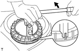 |
While holding the SST by hand, remove the fuel pump gauge retainer.
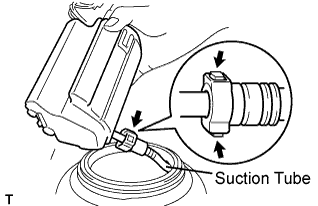 |
Disconnect the fuel suction tube.
Remove the fuel suction tube from the fuel tank.
| 7. REMOVE REAR FLOOR SERVICE HOLE COVER |
 |
Remove the service hole cover and disconnect the fuel sender gauge connector.
| 8. REMOVE FUEL RETURN VENT TUBE SUB-ASSEMBLY |
Disconnect the fuel tank return tube and pump tube.
 |
Remove the 2 tube joint clips and fuel tubes.
|
Using a 6 mm socket, set SST to the fuel pump gauge retainer.
 |
While holding the fuel suction tube by hand, remove the fuel pump gauge retainer.
 |
Remove the fuel return vent tube from the fuel tank.
Remove the No. 1 fuel suction tube set gasket from the fuel tank.
 |
Disconnect the fuel sender gauge connector.
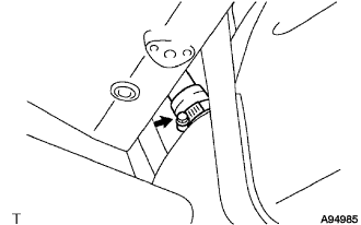
Press down on the sender gauge claw labeled A. Then slide the sender gauge upward.
| 9. REMOVE EXHAUST PIPE ASSEMBLY |
Remove the exhaust pipe (Click here).
| 10. REMOVE FRONT FLOOR COVER CENTER RH |
 |
Remove the 3 nuts, 2 clips and floor cover.
| 11. REMOVE FRONT FLOOR NO. 1 HEAT INSULATOR |
 |
Remove the 4 nuts and heat insulator.
| 12. REMOVE PROPELLER WITH CENTER BEARING SHAFT ASSEMBLY |
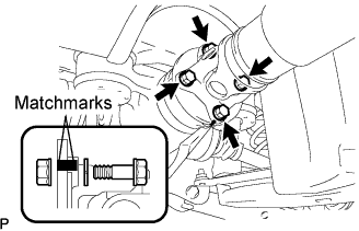 |
Put matchmarks on both flanges.
Remove the 4 nuts, bolts and washers.
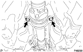 |
Remove the 2 bolts, 2 center support bearing washers and center support bearing.
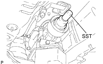 |
Insert SST in the transmission to prevent oil leakage.
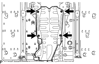
| 13. REMOVE NO. 2 FUEL TANK PROTECTOR |
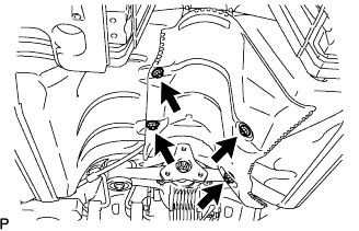 |
Remove the 4 nuts and fuel tank protector.
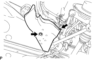
| 14. REMOVE NO. 1 DIFFERENTIAL SUPPORT PROTECTOR |
 |
Remove the 4 nuts and differential support protector.
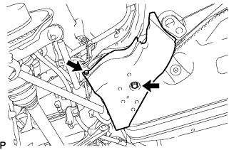
| 15. REMOVE NO. 2 DIFFERENTIAL SUPPORT PROTECTOR |
Remove the 4 nuts and differential support protector.
| 16. REMOVE REAR FLOOR SIDE MEMBER COVER LH |
 |
Remove the 2 bolts and member cover.
| 17. REMOVE REAR FLOOR SIDE MEMBER COVER RH |
 |
Remove the 2 bolts and member cover.
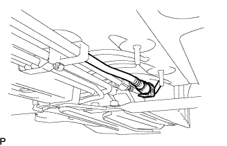
| 18. DISCONNECT PARKING BRAKE CABLE ASSEMBLY |
 |
Remove the 2 parking brake cables from the 4 clamps.
Remove the 4 bolts and disconnect the 2 parking brake cables.
| 19. DISCONNECT FUEL TANK MAIN TUBE SUB-ASSEMBLY |
 |
Pinch and pull the main tube connector to disconnect the connector from the pipe.
| 20. DISCONNECT FUEL RETURN TUBE |
 |
Pinch and pull the return tube connector to disconnect the connector from the pipe.
| 21. DISCONNECT FUEL TANK TO FILLER PIPE HOSE |
 |
Disconnect the filler pipe hose from the fuel tank filler pipe.
| 22. REMOVE FUEL EMISSION HOSE |
 |
Remove the bracket.
Disconnect the 2 fuel emission hoses.
| 23. REMOVE FUEL TANK SUB-ASSEMBLY |
 |
Remove the 2 nuts from the fuel tank.
Place a mission jack under the fuel tank.
Remove the 4 nuts and 2 fuel tank bands.
Slightly lower the mission jack.
| 24. REMOVE FUEL PUMP TUBE SUB-ASSEMBLY |
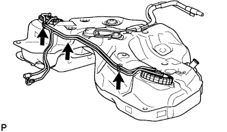 |
Remove the 3 clamps, fuel pump tube and fuel tank main tube.
| 25. REMOVE FUEL TANK CUSHION |
 |
Remove the tank cushions and fuel tank brackets.
| 26. REMOVE NO. 1 FUEL TANK PROTECTOR |
 |
Remove the 2 nuts and fuel tank protector.
