ENGINE IMMOBILISER SYSTEM > TERMINALS OF ECU |
| CHECK ENGINE SWITCH |

Disconnect the L29 switch connector.
Measure the resistance of the wire harness side connector.
| Symbols (Terminal No.) | Wiring Color | Terminal Description | Condition | Specified Condition |
| GND (L29-5) - Body ground | W-B - Body ground | Ground | Always | Below 1 Ω |
Reconnect the L29 switch connector.
Measure the resistance and voltage of the connector.
| Symbols (Terminal No.) | Wiring Color | Terminal Description | Condition | Specified Condition |
| AGND (L29-8) - Body ground | V - Body ground | Ground | Always | Below 1 Ω |
| VC5 (L29-14) - AGND(L29-8) | LG - V*1 O - V*2 | Power supply | Engine immobiliser system is set (key is not in cabin) | Below 1 V |
| VC5 (L29-14) - AGND(L29-8) | LG - V*1 O - V*2 | Power supply | Press engine switch*3 | 4.6 to 5.4 V |
| CODE (L29-10) - AGND (L29-8) | Y - V | Demodulated signal of key code data | Engine immobiliser system is set (key is not in cabin) | Below 1 V |
| CODE (L29-10) - AGND (L29-8) | Y - V | Demodulated signal of key code data | Press engine switch and hold key close to engine switch*3 | Pulse generation (see waveform 1) |
| TXCT (L29-9) - AGND (L29-8) | L - V | Key code output signal | Engine immobiliser system is set (key is not in cabin) | Below 1 V |
| TXCT (L29-9) - AGND (L29-8) | L - V | Key code output signal | Press engine switch and hold key close to engine switch*3 | Pulse generation (see waveform 2) |
Inspect using an oscilloscope.
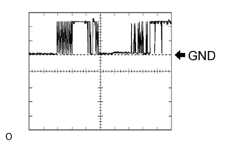 |
Waveform 1 (Reference)
| Item | Content |
| Symbols (Terminal No.) | CODE (L29-10) - AGND (L29-8) |
| Tool Setting | 2 V/DIV., 20 msec./DIV. |
| Condition | Press engine switch and hold key close to engine switch* |
 |
Waveform 2 (Reference)
| Item | Content |
| Symbols (Terminal No.) | TXCT (L29-9) - AGND (L29-8) |
| Tool Setting | 2 V/DIV., 20 msec./DIV. |
| Condition | Press engine switch and hold key close to engine switch* |
| CHECK CERTIFICATION ECU |

Disconnect the V28 ECU connector.
Measure the resistance and voltage of the wire harness side connector.
| Symbols (Terminal No.) | Wiring Color | Terminal Description | Condition | Specified Condition |
| E (V28-17) - Body ground | W-B - Body ground | Ground | Always | Below 1 Ω |
| +B1 (V28-1) - E (V28-17) | R - W-B | +B power supply | Always | 10 to 14 V |
| IG (V28-18) - E (V28-17) | B - W-B | Ignition power supply | Engine switch off | Below 1 V |
Reconnect the V28 connector.
Measure the resistance and voltage of the connector.
| Symbols (Terminal No.) | Wiring Color | Terminal Description | Condition | Specified Condition |
| AGND (V28-40) - Body ground | V - Body ground | Engine switch ground | Always | Below 1 Ω |
| VC5 (V28-30) - AGND(V28-40) | O - V | Engine switch power supply | Engine immobiliser system is set (key is not in cabin) | Below 1 V |
| VC5 (V28-30) - AGND(V28-40) | O - V | Engine switch power supply | Press engine switch* | 4.6 to 5.4 V |
| CODE (V28-9) - AGND (V28-40) | Y - V | Engine switch CODE input | Engine immobiliser system is set (key is not in cabin) | Below 1 V |
| CODE (V28-9) - AGND (V28-40) | Y - V | Engine switch CODE input | Press engine switch and hold key close to engine switch* | Pulse generation (see waveform 1) |
| TXCT (V28-8) - AGND (V28-40) | L - V | Engine switch TX output | Engine immobiliser system is set (key is not in cabin) | Below 1 V |
| TXCT (V28-8) - AGND (V28-40) | L - V | Engine switch TX output | Press engine switch and hold key close to engine switch* | Pulse generation (see waveform 2) |
Inspect using an oscilloscope.
|
Waveform 1 (Reference)
| Item | Content |
| Symbols (Terminal No.) | CODE (V28-9) - AGND (V28-40) |
| Tool Setting | 2 V/DIV., 20 msec./DIV. |
| Condition | Press engine switch and hold key close to engine switch* |
|
Waveform 2 (Reference)
| Item | Content |
| Symbols (Terminal No.) | TXCT (V28-8) - AGND (V28-40) |
| Tool Setting | 2 V/DIV., 20 msec./DIV. |
| Condition | Press engine switch and hold key close to engine switch* |
| CHECK IMMOBILISER CODE ECU |

Disconnect the L58 ECU connector.
Measure the resistance and voltage of the wire harness side connector.
| Symbols (Terminal No.) | Wiring Color | Terminal Description | Condition | Specified Condition |
| GND (L58-8) - Body ground | W-B - Body ground | Ground | Always | Below 1 Ω |
| +B (L58-1) - GND (L58-8) | G - W-B | +B power supply | Always | 10 to 14 V |
Reconnect the L58 ECU connector.
Measure the voltage of the connector.
| Symbols (Terminal No.) | Wiring Color | Terminal Description | Condition | Specified Condition |
| EFII (L58-5) - GND (L58-8) | P - W-B | ECM input signal | Engine switch off | Below 1 V |
| EFII (L58-5) - GND (L58-8) | P - W-B | ECM input signal | Engine switch on (IG) | Pulse generation (see waveform 1) |
| EFIO(L58-6) - GND (L58-8) | LG - W-B | ECM output signal | Engine switch off | Below 1 V |
| EFIO (L58-6) - GND (L58-8) | LG - W-B | ECM output signal | Engine switch on (IG) | Pulse generation (see waveform 2) |
Inspect using an oscilloscope.
 |
Waveform 1 (Reference)
| Item | Content |
| Symbols (Terminal No.) | EFII (L58-5) - GND (L58-8) |
| Tool Setting | 10 V/DIV., 100 msec./DIV. |
| Condition | Engine switch on (IG) |
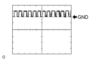 |
Waveform 2 (Reference)
| Item | Content |
| Symbols (Terminal No.) | EFIO (L58-6) - GND (L58-8) |
| Tool Setting | 10 V/DIV., 100 msec./DIV. |
| Condition | Engine switch on (IG) |
| CHECK POWER SOURCE CONTROL ECU |

Disconnect the L73 ECU connector.
Measure the resistance and voltage of the wire harness side connector.
| Symbols (Terminal No.) | Wiring Color | Terminal Description | Condition | Specified Condition |
| GND2 (L73-6) - Body ground | W-B - Body ground | Ground | Always | Below 1 Ω |
| AM2 (L73-12) - Body ground | BR -Body ground | +B power supply | Always | 10 to 14 V |
| AM1 (L73-33) - Body ground | O -Body ground | +B power supply | Always | 10 to 14 V |
| CHECK STEERING LOCK ECU |

Disconnect the L28 ECU connector.
Measure the resistance and voltage of the wire harness side connector.
| Symbols (Terminal No.) | Wiring Color | Terminal Description | Condition | Specified Condition |
| SGND (L28-2) - Body ground | W-B - Body ground | Ground | Always | Below 1 Ω |
| GND (L28-1) - Body ground | W-B - Body ground | Ground | Always | Below 1 Ω |
| B (L28-7) - Body ground | L - Body ground | +B power supply | Always | 10 to 14 V |
| IG2 (L28-6) - Body ground | B - Body ground | Ignition power supply | Engine switch off | 0 V |
| IG2 (L28-6) - Body ground | B - Body ground | Ignition power supply | Engine switch on (IG) | 10 to 14 V |
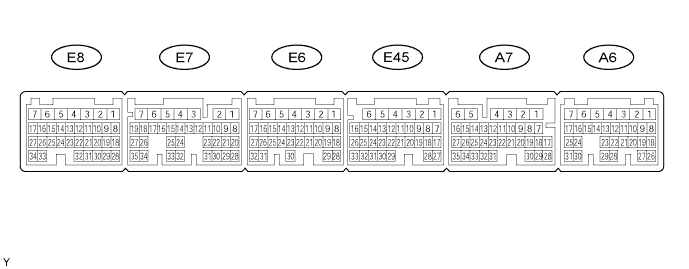
| CHECK ECM (3GR-FSE, 3GR-FE) |
Measure the resistance and voltage of the connector.
| Symbols (Terminal No.) | Wiring Color | Terminal Description | Condition | Specified Condition |
| E1 (E7-7) - Body ground | W-B - Body ground | Ground | Always | Below 1 Ω |
| E01 (E6-2) - Body ground | W-B - Body ground | Ground | Always | Below 1 Ω |
| E02 (E6-1) - Body ground | W-B - Body ground | Ground | Always | Below 1 Ω |
| E03 (E8-6) - Body ground | W-B - Body ground | Ground | Always | Below 1 Ω |
| E04 (E45-5) - Body ground | W-B - Body ground | Ground | Always | Below 1 Ω |
| E05 (E45-3) - Body ground | W-B - Body ground | Ground | Always | Below 1 Ω |
| EC (A6-2)- Body ground | W-B - Body ground | Ground | Always | Below 1 Ω |
| ME01 (E8-4) - Body ground | W-B - Body ground | Ground | Always | Below 1 Ω |
| BATT (A6-4) - E1 (E7-7) | L - BR | Battery (for measuring battery voltage and for ECM memory) | Always | 10 to 14 V |
| +B (A6-6) - E1 (E7-7) | B-R - BR | Power source of ECM | Engine switch off | Below 1 V |
| +B (A6-6) - E1 (E7-7) | B-R - BR | Power source of ECM | Engine switch on (IG) | 10 to 14 V |
| +B1 (A6-5) - E1 (E7-7) | B-R - BR | Power source of ECM | Engine switch off | Below 1 V |
| +B1 (A6-5) - E1 (E7-7) | B-R - BR | Power source of ECM | Engine switch on (IG) | 10 to 14 V |
| IMI (A7-6) - E1 (E7-7) | W-B - BR | Immobiliser code ECU input signal | Engine switch off | Below 1 V |
| IMI (A7-6) - E1 (E7-7) | W-B - BR | Immobiliser code ECU input signal | Engine switch on (IG) | Pulse generation (see waveform 1) |
| IMO (A7-7) - E1 (E7-7) | W-B - BR | Immobiliser code ECU output signal | Engine switch off | Below 1 V |
| IMO (A7-7) - E1 (E7-7) | W-B - BR | Immobiliser code ECU output signal | Engine switch on (IG) | Pulse generation (see waveform 2) |
Inspect using an oscilloscope.
|
Waveform 1 (Reference)
| Item | Content |
| Symbols (Terminal No.) | IMI (A7-6) - E1 (E7-7) |
| Tool Setting | 10 V/DIV., 100 msec./DIV. |
| Condition | Engine switch on (IG) |
|
Waveform 2 (Reference)
| Item | Content |
| Symbols (Terminal No.) | IMO (A7-7) - E1 (E7-7) |
| Tool Setting | 10 V/DIV., 100 msec./DIV. |
| Condition | Engine switch on (IG) |
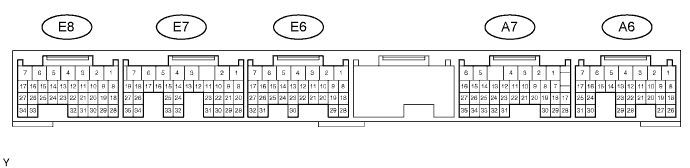
| CHECK ECM (3UZ-FE) |
Measure the voltage and resistance of the connector.
| Symbols (Terminal No.) | Wiring Color | Terminal Description | Condition | Specified Condition |
| E1 (E7-7) - Body ground | W-B - Body ground | Ground | Always | Below 1 Ω |
| E01 (E6-2) - Body ground | W-B - Body ground | Ground | Always | Below 1 Ω |
| E02 (E6-1) - Body ground | W-B - Body ground | Ground | Always | Below 1 Ω |
| E03 (E8-6) - Body ground | W-B - Body ground | Ground | Always | Below 1 Ω |
| EC (A6-2) - Body ground | W-B - Body ground | Ground | Always | Below 1 Ω |
| ME01 (E8-4) - Body ground | W-B - Body ground | Ground | Always | Below 1 Ω |
| BATT (A6-4) - E1 (E7-7) | L - BR | Battery (for measuring battery voltage and for ECM memory) | Always | 10 to 14 V |
| +B (A6-6) - E1 (E7-7) | B-R - BR | Power source of ECM | Engine switch off | Below 1 V |
| +B (A6-6) - E1 (E7-7) | B-R - BR | Power source of ECM | Engine switch on (IG) | 10 to 14 V |
| +B1 (A6-5) - E1 (E7-7) | B-R - BR | Power source of ECM | Engine switch off | Below 1 V |
| +B1 (A6-5) - E1 (E7-7) | B-R - BR | Power source of ECM | Engine switch on (IG) | 10 to 14 V |
| IMI (A7-6) - E1 (E7-7) | W-B - BR | Immobiliser code ECU input signal | Engine switch off | Below 1 V |
| IMI (A7-6) - E1 (E7-7) | W-B - BR | Immobiliser code ECU input signal | Engine switch on (IG) | Pulse generation (see waveform 1) |
| IMO (A7-7) - E1 (E7-7) | W-B - BR | Immobiliser code ECU output signal | Engine switch off | Below 1 V |
| IMO (A7-7) - E1 (E7-7) | W-B - BR | Immobiliser code ECU output signal | Engine switch on (IG) | Pulse generation (see waveform 2) |
Inspect using an oscilloscope.
|
Waveform 1 (Reference)
| Item | Content |
| Symbols (Terminal No.) | IMI (A7-6) - E1 (E7-7) |
| Tool Setting | 10 V/DIV., 100 msec./DIV. |
| Condition | Engine switch on (IG) |
|
Waveform 2 (Reference)
| Item | Content |
| Symbols (Terminal No.) | IMO (A7-7) - E1 (E7-7) |
| Tool Setting | 10 V/DIV., 100 msec./DIV. |
| Condition | Engine switch on (IG) |
| CHECK COWL SIDE JUNCTION BLOCK RH (MULTIPLEX NETWORK BODY ECU) |
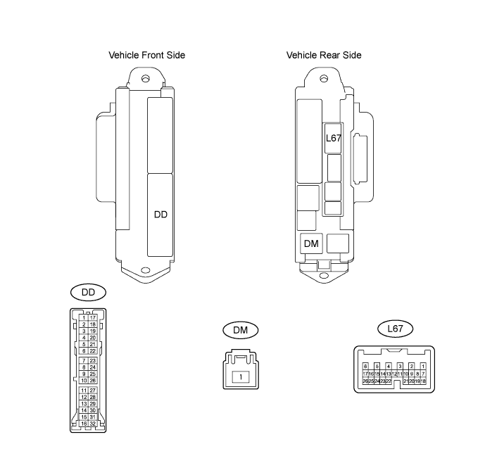
Disconnect the DD and DM junction block connectors.
Measure the resistance and voltage of the wire harness side connectors.
| Symbols (Terminal No.) | Wiring Color | Terminal Description | Condition | Specified Condition |
| GND2 (DD-7) - Body ground | W-B - Body ground | Ground | Always | Below 1 Ω |
| IG (DM-1) - Body ground | B - Body ground | Ignition power supply | Engine switch off | Below 1 V |
| IG (DM-1) - Body ground | B - Body ground | Ignition power supply | Engine switch on (IG) | 10 to 14 V |
Reconnect the DD and DM junction block connectors.
Measure the voltage of the connector.
| Symbols (Terminal No.) | Wiring Color | Terminal Description | Condition | Specified Condition |
| IND (L67-24) - Body ground | LG - Body ground | Indicator light signal | Key is not in cabin (immobiliser system is not set) | Alternating between 10 to 14 V (0.2 seconds) to below 1 V |
