IGNITION SYSTEM > ON-VEHICLE INSPECTION |
| 1. PERFORM SPARK TEST |
Check for DTCs.
Check if sparks occur.
Remove the ignition coil.
Remove the spark plug.
Install the spark plug to the ignition coil and connect the ignition coil connector.
Disconnect the 6 injector connectors.
Ground the spark plug.
Visually check that sparks occur while the engine is being cranked.
Perform the spark test according to the flowchart below.
Check that the wire harness side connector of the ignition coil with igniter is securely connected.
| Result | Proceed to |
| NG | Connect securely |
| OK | Go to next step |
Perform a spark test on each ignition coil with igniter.
| Result | Proceed to |
| OK | Replace ignition coil with igniter |
| NG | Go to next step |
Check the power supply to the ignition coil with igniter.
| Result | Proceed to |
| NG | Check wiring between engine switch and ignition coil with igniter |
| OK | Go to next step |
Check the VVT sensor output voltage.
| Result | Proceed to |
| NG | Check that there is resistance between ECM and VVT sensor. If there is no resistance, replace VVT sensor. If there is resistance, repair wiring between VVT sensor and ECM |
| OK | Go to next step |
Check the resistance of the crankshaft position sensor.
| Temperature | Specified Condition |
| Cold | 1,630 to 2,740 Ω |
| Hot | 2,065 to 3,225 Ω |
| Result | Proceed to |
| NG | Replace crankshaft position sensor |
| OK | Go to next step |
Check the IGT signal from the ECM.
| Result | Proceed to |
| NG | Check ECM |
| OK | Repair wiring between ignition coil and ECM |
Using a 16 mm plug wrench, install the spark plug.
Install the ignition coils.
| 2. CHECK VVT SENSOR OUTPUT VOLTAGE |
Turn the engine switch on (IG).
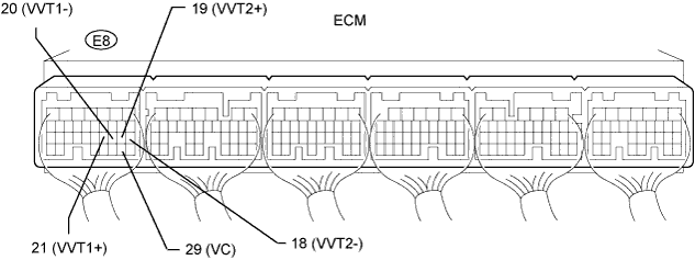
Check the voltage between the terminal.
| Tester Connection | Condition | Specified Condition |
| E8-29 (VC) - Body ground | Engine switch on (IG) | 5 V |
While turning the crankshaft pulley by hand, measure the voltage between each terminal. Check that the voltage changes between the Hi range and Lo range shown in the table below.
| Sensor Position | Terminal No. | Voltage (Hi) | Voltage (Lo) |
| Bank 1 | VVT1+ (E8-21) - VVT1- (E8-20) | 3.375 to 4.950 V | 0.450 to 1.375 V |
| Bank 2 | VVT2+ (E8-19) - VVT2- (E8-18) | 3.375 to 4.950 V | 0.450 to 1.375 V |
| 3. CHECK SPARK PLUG |
 |
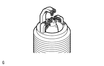
Check the electrode.
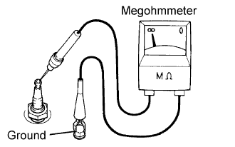
Using a megohmmeter, measure the insulation resistance.
 |
Alternative inspection method:
Quickly accelerate the engine to 4,000 rpm 5 times.
Remove the spark plug.
Visually check the spark plug.
If the electrode is dry, the spark plug is functioning properly. If the electrode is damp, proceed to the next step.
Check the spark plug for any damage on its threads and insulator.
| DENSO made | FK20HBR11 |
| NGK made | ILFR6D11T |
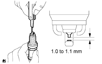 |
Check the spark plug electrode gap.
