ENGINE UNIT > INSPECTION |
| 1. INSPECT CAMSHAFT |
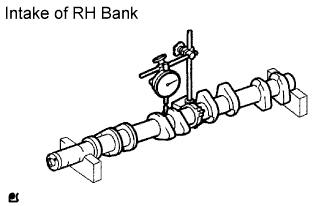 |
Inspect the circle runout.
Place the camshaft on V-blocks.
Using a dial indicator, measure the circle runout at the center journal.
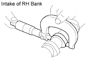 |
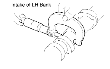
Using a micrometer, measure the cam lobe height.
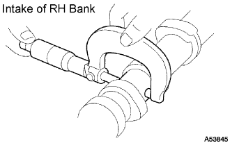 |
Inspect the journal diameter of the camshaft.
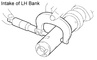
Using a micrometer, measure the journal diameter of the camshaft for the camshaft bearing.
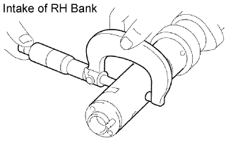 |
Using a micrometer, measure the journal diameter for the camshaft timing tube.
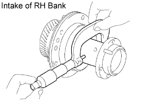 |
Inspect the journal diameter of the camshaft timing tube.
Using a micrometer, measure the journal diameter.
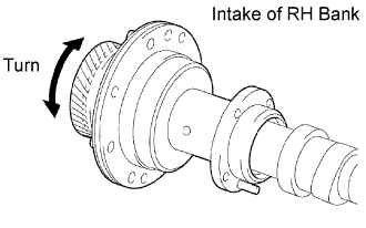 |
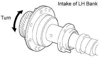
Install the camshaft timing tube to the camshaft, and check that the timing tube turns smoothly.
 |
Check the oil clearance.
Install the camshaft timing tube to the camshaft.
Clean the bearing caps and journals.
Check the bearings for flaking and scoring.
Place the camshaft on the cylinder head.
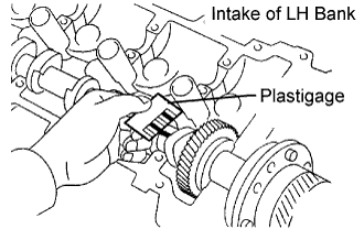
Lay a strip of Plastigage across each of the journals.
Install the bearing caps.
Remove the bearing caps.
 |
Measure the Plastigage at its widest point.
| Journal | Oil clearance |
| Camshaft journal | 0.030 to 0.067 mm (0.0012 to 0.0026 in.) |
| Camshaft timing tube journal | 0.036 to 0.057 mm (0.0014 to 0.0022 in.) |
| Journal | Oil clearance |
| Camshaft journal | 0.100 mm (0.0039 in.) |
| Camshaft timing tube journal | 0.075 mm (0.0030 in.) |
Completely remove the Plastigage.
Remove the camshaft.
Remove the camshaft timing tube from the camshaft.
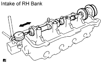 |
Check the thrust clearance.
Install the camshaft timing tube to the camshaft.
Install the camshaft.
Using a dial indicator, measure the thrust clearance while moving the camshaft back and forth.
Remove the camshaft.
Remove the camshaft timing tube from the camshaft.
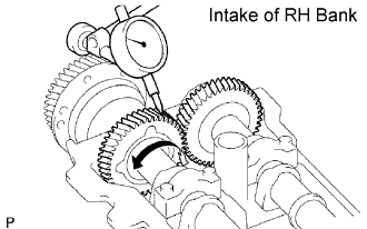 |
Check the gear backlash.
Install the drive gear to the camshaft timing tube.
Install the camshaft timing tube to the camshaft.
Install the camshaft and No. 2 camshaft without installing the camshaft sub-gear and front bearing cap.
Using a dial indicator, measure the backlash.
Remove the camshaft and No. 2 camshaft.
Remove the camshaft timing tube from the camshaft.
Remove the drive gear from the camshaft timing tube.
| 2. INSPECT NO. 3 CAMSHAFT SUB-ASSEMBLY |
 |
Inspect the circle runout.
Place the camshaft on V-blocks.
Using a dial indicator, measure the circle runout at the center journal.
 |
Using a micrometer, measure the cam lobe height.
 |
Inspect the journal diameter of the camshaft.
Using a micrometer, measure the journal diameter of the No. 3 camshaft for the camshaft bearing.
 |
Using a micrometer, measure the journal diameter for the camshaft timing tube.
 |
Inspect the journal diameter of the camshaft timing tube.
Using a micrometer, measure the journal diameter.
 |
Install the timing tube to the No. 3 camshaft, and check the timing tube turns smoothly.
 |
Check the oil clearance.
Install the camshaft timing tube to the No. 3 camshaft.
Clean the bearing caps and journals.
Check the bearings for flaking and scoring.
Place the No. 3 camshaft on the cylinder head.
Lay a strip of Plastigage across each of the journals.
Install the bearing caps.
Remove the bearing caps.
 |
Measure the Plastigage at its widest point.
| Journal | Oil clearance |
| Camshaft journal | 0.030 to 0.067 mm (0.0012 to 0.0026 in.) |
| Camshaft timing tube journal | 0.036 to 0.057 mm (0.0014 to 0.0022 in.) |
| Journal | Oil clearance |
| Camshaft journal | 0.100 mm (0.0039 in.) |
| Camshaft timing tube journal | 0.075 mm (0.0030 in.) |
Completely remove the Plastigage.
Remove the camshaft.
Remove the camshaft timing tube from the No. 3 camshaft.
 |
Check the thrust clearance.
Install the camshaft timing tube to the No. 3 camshaft.
Install the No. 3 camshaft.
Using a dial indicator, measure the thrust clearance while moving the No. 3 camshaft back and forth.
Remove the No. 3 camshaft.
Remove the camshaft timing tube from the No. 3 camshaft.
 |
Check the gear backlash.
Install the drive gear to the camshaft timing tube.
Install the camshaft timing tube to the No. 3 camshaft.
Install the No. 3 camshaft and No. 4 camshaft without installing the camshaft sub-gear and front bearing cap.
Using a dial indicator, measure the backlash.
Remove the No. 3 camshaft and No. 4 camshaft.
Remove the camshaft timing tube from the No. 3 camshaft.
Remove the drive gear from the camshaft timing tube.
| 3. INSPECT CYLINDER HEAD SUB-ASSEMBLY |
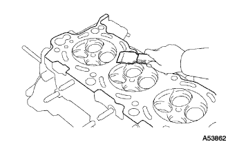 |
Clean the cylinder head.
Using a gasket scraper, remove all the gasket material from the cylinder block contact surface.
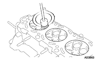 |
Using a wire brush, remove all the carbon from the combustion chambers.
 |
Using a valve guide bushing brush and solvent, clean all the guide bushes.
 |
Using a soft brush and solvent, thoroughly clean the cylinder head.
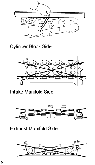 |
Inspect for flatness.
Using a precision straightedge and feeler gauge, measure the surfaces contacting the cylinder block and the manifolds for warpage.
| Item | Specified Condition |
| Cylinder block surface | 0.05 mm (0.0020 in.) |
| Intake manifold surface | 0.10 mm (0.0039 in.) |
| Exhaust manifold surface | 0.10 mm (0.0039 in.) |
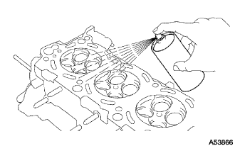 |
Inspect the cylinder head for cracks.
Using a dye penetrant, check the combustion chamber, intake ports, exhaust ports and cylinder block surface for cracks.
| 4. INSPECT CYLINDER BLOCK SUB-ASSEMBLY |
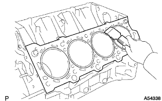 |
Clean the cylinder block.
Using a gasket scraper, remove all the gasket material from the top surface of the cylinder block.
Using a soft brush and solvent, thoroughly clean the cylinder block.
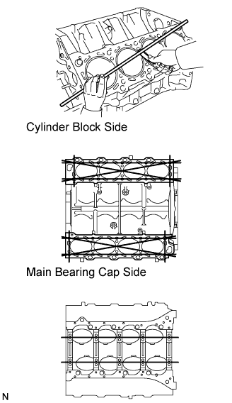 |
Inspect for flatness.
Using a precision straightedge and feeler gauge, measure the surfaces contacting the cylinder head and main bearing cap for warpage.
 |
Visually check the cylinder for vertical scratches.
If deep scratches are present, replace the cylinder block.
 |
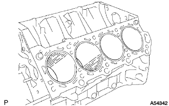
Inspect the cylinder bore diameter.
  |
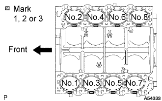
Using a cylinder gauge, measure the cylinder bore diameter at positions A and B in the thrust and axial directions.
| Number Mark | Specified Condition |
| Mark 1 | 91.000 to 91.008 mm (3.5827 to 3.5830 in.) |
| Mark 2 | 91.008 to 91.021 mm (3.5830 to 3.5835 in.) |
| Mark 3 | 91.021 to 91.029 mm (3.5835 to 3.5838 in.) |
| 5. INSPECT PISTON SUB-ASSEMBLY WITH PIN |
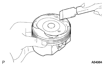 |
Clean the piston.
Using a gasket scraper, remove the carbon from the piston top.
 |
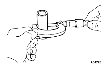
Using a groove cleaning tool or broken ring, clean the piston ring grooves.
 |
Using solvent and a brush, thoroughly clean the piston.
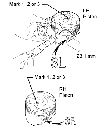 |
Inspect the piston oil clearance.
Using a micrometer, measure the piston diameter at right angles to the piston pin center line, 28.1 mm (1.106 in.) from the piston head.
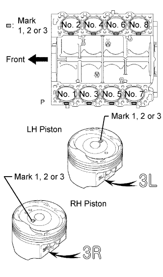
| Number Mark | Specified Condition |
| Mark 1 | 90.910 to 90.920 mm (3.5791 to 3.5795 in.) |
| Mark 2 | 90.920 to 90.928 mm (3.5795 to 3.5798 in.) |
| Mark 3 | 90.928 to 90.938 mm (3.5798 to 3.5802 in.) |
Measure the cylinder bore diameter in the thrust directions.
 |
Subtract the piston diameter measurement from the cylinder bore diameter measurement.
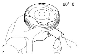 |
Inspect the piston pin fit.
At 60°C (140°F), check that the piston pin can be pushed into the piston pin hole with your thumb.
 |
Using a micrometer, measure the piston pin diameter.
| 6. INSPECT PISTON RING SET |
 |
Inspect the piston ring groove clearance.
Using a feeler gauge, measure the clearance between a new piston ring and the wall of the ring groove.
| Piston Ring | Specified Condition |
| No. 1 | 0.030 to 0.080 mm (0.0012 to 0.0031 in.) |
| No. 2 | 0.020 to 0.060 mm (0.0008 to 0.0024 in.) |
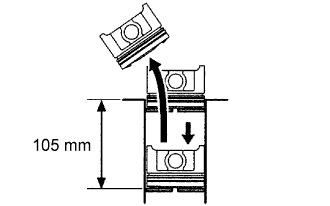 |
Inspect the piston ring end gap.
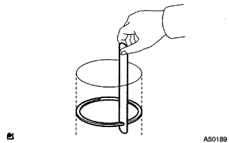
Insert the piston ring into the cylinder bore.
Using a piston, push the piston ring a little beyond the bottom of the ring travel 105 mm (4.13 in.) from the top of the cylinder block.
 |
Using a feeler gauge, measure the end gap.
| End Gap | Specified Condition |
| No. 1 piston ring | 0.300 to 0.400 mm (0.0118 to 0.0157 in.) |
| No. 2 piston ring | 0.400 to 0.500 mm (0.0157 to 0.0197 in.) |
| Oil ring (Side rail) | 0.150 to 0.400 mm (0.0059 to 0.0157 in.) |
| End Gap | Specified Condition |
| No. 1 piston ring | 1.10 mm (0.0433 in.) |
| No. 2 piston ring | 1.20 mm (0.0472 in.) |
| Oil ring (Side rail) | 1.10 mm (0.0433 in.) |
| 7. INSPECT CONNECTING ROD SUB-ASSEMBLY |
 |
Using a rod aligner and feeler gauge, check the connecting rod alignment.
Check if the connecting rod is bent.
 |
Check if the connecting rod is twisted.
| 8. INSPECT PISTON PIN OIL CLEARANCE |
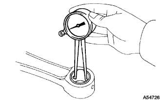 |
Inspect the piston pin oil clearance.
Using a caliper gauge, measure the inside diameter of the connecting rod bushing.
Subtract the piston pin diameter measurement from the bush inside diameter measurement.
| 9. INSPECT CONNECTING ROD BOLT |
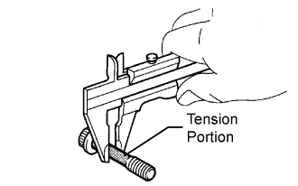 |
Using a vernier caliper, measure the tension portion of the connecting rod bolt.
| 10. INSPECT CRANKSHAFT BEARING CAP BOLT |
 |
Using a vernier caliper, measure the tension portion diameter of the main bearing cap bolt.
| 11. INSPECT CRANKSHAFT |
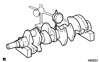 |
Inspect for circle runout.
Place the crankshaft on V-blocks.
Using a dial indicator, measure the circle runout at the center journal.
 |
Inspect the main journals and crank pins.
Using a micrometer, measure the diameter of each main journal and crank pin.
Check each main journal and crank pin for taper and out of round as shown in the illustration.
