ENGINE UNIT > REASSEMBLY |
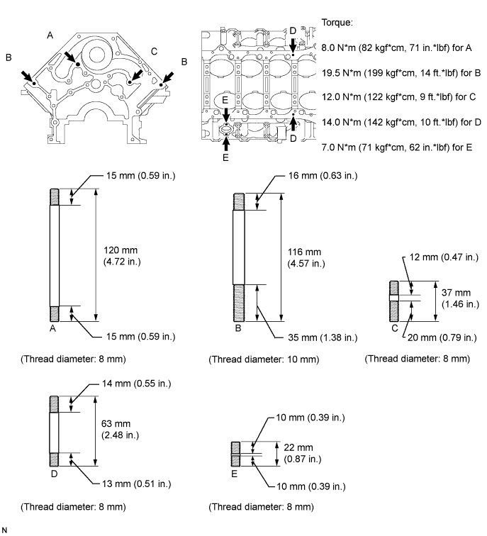
| 1. INSTALL STUD BOLT |
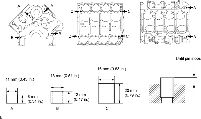
| 2. INSTALL STRAIGHT PIN |

| 3. INSTALL RING PIN |
| 4. INSTALL PISTON SUB-ASSEMBLY WITH PIN |
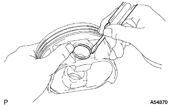 |
Using a small screwdriver, install a new snap ring on one side of the piston pin hole.
 |
Gradually heat the piston to about 60°C (140°F).
 |
Coat the piston pin with engine oil.
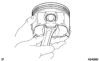
The piston's front mark and the connecting rod's outside mark should face the same direction, as shown in the illustration.
Align the piston pin holes of the piston and connecting rod, and push in the piston pin with your thumb.
 |
Check the fit between the piston and piston pin.
Try to move the piston back and forth on the piston pin.
 |
Using a small screwdriver, install a new snap ring on the other side of the piston pin hole.
 |
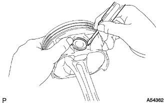
Install the oil ring expander and 2 side rails by hand.
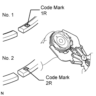
Using a piston ring expander, install the No. 1 and No. 2 piston rings with the code mark facing upward.
| Piston Ring | Code Mark |
| No. 1 | 1R |
| No. 2 | 2R |
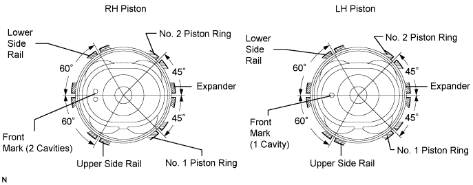
Position the piston rings so that the ring ends are as shown in the illustration.
| 5. INSTALL CONNECTING ROD BEARING |
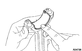 |
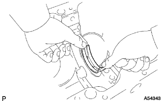
Align the bearing claw with the groove of the connecting rod or connecting cap.
Install the bearings in the connecting rod and connecting rod cap.
| 6. INSTALL CRANKSHAFT BEARING |
 |
 |
Align the bearing claw with the claw groove of the cylinder block, and push in the 5 upper bearings.
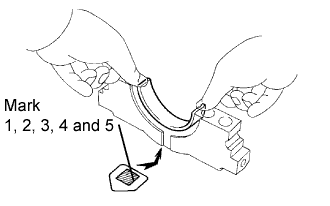 |
Align the bearing claw with the claw groove of the crankshaft bearing cap, and push in the 5 lower bearings.
| 7. INSTALL CRANKSHAFT THRUST WASHER SET |
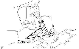 |
Install the 2 thrust washers under the No. 3 journal position of the cylinder block with the oil grooves facing outward.
 |
Install the 2 thrust washers on the No. 3 bearing cap with the grooves facing outward.
| 8. INSTALL CRANKSHAFT |
 |
Place the crankshaft on the cylinder block.
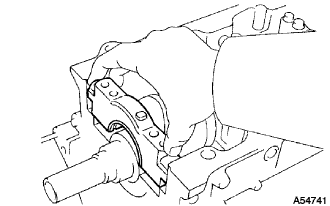 |
Install the 5 crankshaft bearing caps in their proper locations.
 |
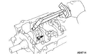
Install the crankshaft bearing cap bolts.
Apply a light coat of engine oil on the threads and under the crankshaft bearing cap bolts.
Install and uniformly tighten the 20 crankshaft bearing cap bolts in several passes in the sequence shown in the illustration.
 |
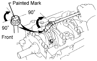
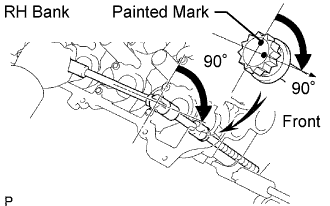
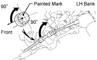
Mark the front of the crankshaft bearing cap bolt's head with paint.
Tighten the crankshaft bearing cap bolts another 90° as shown in the illustration.
Check that the painted mark is now at a 90° angle to the front.
 |
Install a new seal washer to the crankshaft bearing cap bolt.
Install and uniformly tighten the 10 crankshaft bearing cap bolts.
Check that the crankshaft turns smoothly.
Check the crankshaft thrust clearance.
| 9. INSTALL PISTON AND CONNECTING ROD |
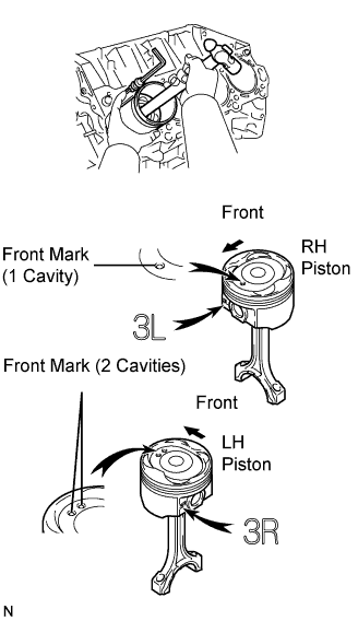 |
Using a piston ring compressor, push the correctly numbered piston and connecting rod assemblies into each cylinder with the front mark of the piston facing forward.
 |
Place the connecting rod cap on the connecting rod.
Match the numbered connecting rod cap with the connecting rod.
Align the pin groove of the connecting rod cap with the pins of the connecting rod, and install the connecting rod cap.
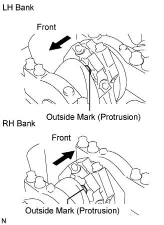 |
Check that the outside mark of the connecting rod cap is facing in the correct direction.
 |
Install the connecting rod cap bolts.
Apply a light coat of engine oil on the threads and under the heads of the connecting rod cap bolts.
Install and alternately tighten the 2 connecting rod cap bolts in several passes.
 |
Mark the front of the connecting cap bolt with paint.
Tighten the cap bolts another 90° as shown in the illustration.
Check that the painted mark is now at a 90° angle to the front.
Check that the crankshaft turns smoothly.
Check the connecting rod thrust clearance.
| 10. INSTALL WATER SEAL PLATE |
Remove any old packing (FIPG) material.
 |
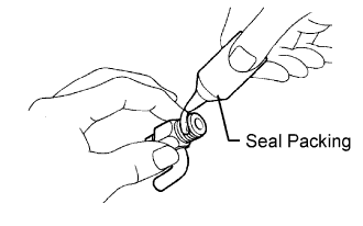
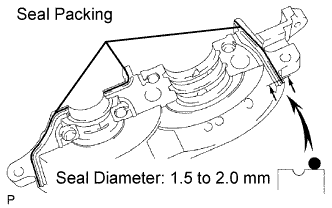
Apply seal packing to the seal plate as shown in the illustration.
Install the seal plate with the 2 nuts. Alternately tighten the nuts in several passes.
| 11. INSTALL CYLINDER BLOCK WATER DRAIN COCK SUB-ASSEMBLY |
 |
Apply seal packing to 2 or 3 threads.
 |
Install the RH and LH drain cocks.
| 12. INSTALL CAMSHAFT SETTING OIL SEAL |
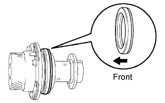 |
Place a new oil seal into the timing tube.
| 13. INSTALL CAMSHAFT TIMING TUBE ASSEMBLY |
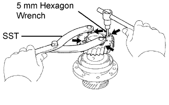 |
Align the timing tube knock pin with the knock pin groove of the drive gear, and temporarily install the drive gear with the 4 bolts.
Using SST and a 5 mm hexagon wrench, uniformly tighten the 4 bolts in several passes.
 |
Mount the hexagon wrench head portion of the camshaft in a vise.
 |
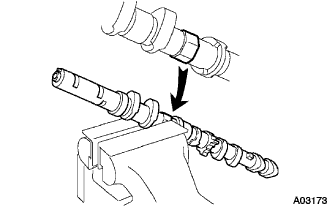
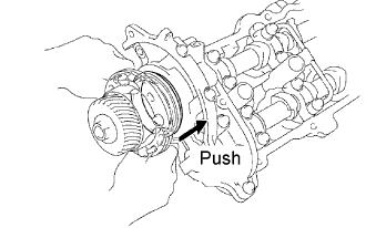
Align the camshaft knock pin with the knock pin groove of the timing tube, and push the timing tube by hand until it touches the bottom.
Using a 10 mm hexagon wrench, install the bolt.
Install the seal washer and screw plug.
| 14. INSTALL CAMSHAFT SUB GEAR |
 |
Install the bolt washer (1), sub gear (2) and wave washer (3).
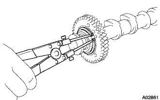 |
Using snap ring pliers, install the snap ring.
 |
Mount the hexagon wrench head portion of the camshaft in a vise.
 |
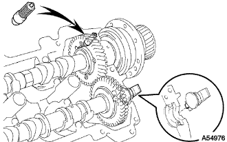
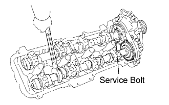
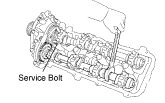
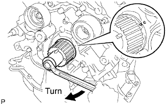
Using SST, align the holes of the driven main gear and sub gear by turning the sub gear clockwise, and temporarily install a service bolt.
Align the gear teeth of the driven main gear and sub gear, and tighten the service bolt.
| 15. INSTALL ENGINE REAR OIL SEAL RETAINER |
Remove any oil packing (FIPG) material.
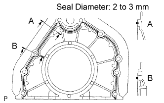 |
Apply seal packing to the oil seal retainer as shown in the illustration.
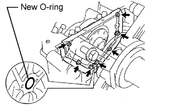 |
Install a new O-ring to the cylinder block.
Install the oil seal retainer with the 7 bolts.
| 16. INSTALL OIL PUMP ASSEMBLY |
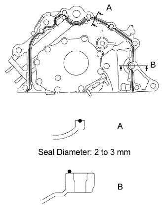 |
Apply seal packing to the oil pump as shown in the illustration.
 |
Apply engine oil to a new O-ring.
Install the O-ring to the cylinder block.
Align the spline teeth of the oil pump drive gear with the large teeth of the crankshaft, and slide the oil pump onto the crankshaft.
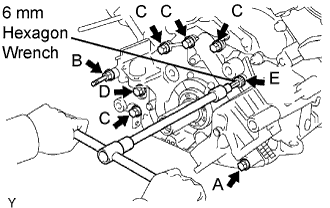 |
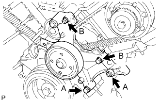
Install the oil pump with a new stud bolt and the 7 bolts. Uniformly tighten the bolts in several passes.
| Bolt | Bolt Head Size | Length |
| A | 12 mm bolt | 50 mm (1.97 in.) |
| B | 12 mm stud bolt | 106 mm (4.17 in.) |
| C | 12 mm | 30 mm (1.18 in.) |
| D | 14 mm | 44 mm (1.73 in.) |
| E | 6 mm hexagon bolt | 28 mm (1.10 in.) |
| 17. INSTALL OIL STRAINER SUB-ASSEMBLY |
 |
Install a new gasket and the oil strainer with the 2 bolts and 2 nuts.
| 18. INSTALL OIL PAN STUD BOLT |
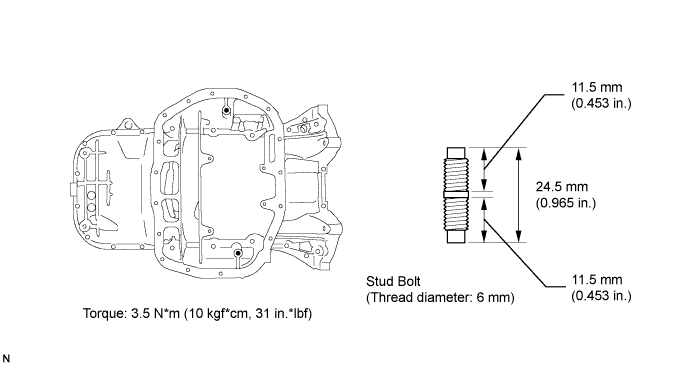
| 19. INSTALL OIL PAN SUB-ASSEMBLY |
 |
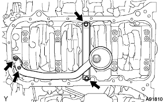
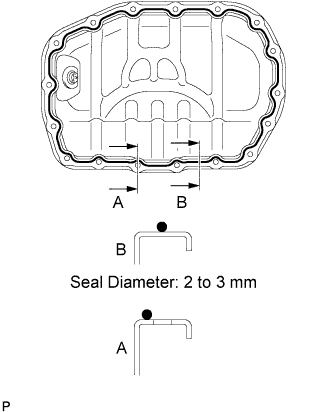
Apply the seal packing as shown in the illustration.
 |
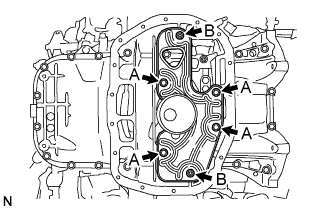
Temporarily install the oil pan with the 18 bolts, stud bolt and 2 nuts.
| Bolt | Bolt Head Size | Length |
| A | 10 mm | 22 mm (0.87 in.) |
| B | 12 mm | 25 mm (0.99 in.) |
| C | 12 mm | 60 mm (2.38 in.) |
| D | 10 mm | 35 mm (1.38 in.) |
Set the oil pan as shown in the illustration.
Uniformly tighten the bolts and nuts in several passes.
| 20. INSTALL OIL PAN BAFFLE PLATE |
 |
Install the baffle plate with the 4 bolts and 2 nuts.
| 21. INSTALL NO. 2 OIL PAN SUB-ASSEMBLY |
 |
Apply seal packing as shown in the illustration.
Install the oil pan with the 15 bolts and 2 nuts. Uniformly tighten the bolts and nuts in several passes.
| 22. INSTALL WATER PUMP ASSEMBLY |
 |
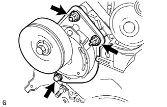
Install a new gasket and the water pump with the 5 bolts, 2 stud bolts and nut. Uniformly tighten the bolts, stud bolts and nut in several passes.
| 23. INSTALL CYLINDER HEAD SUB-ASSEMBLY |
 |
Place a new cylinder head gasket on the cylinder block.
Place the cylinder head on the cylinder head gasket.
 |
Install the cylinder head bolts.
Apply a light coat of engine oil on the threads and under the heads of the cylinder head bolts.
Install the plate washer to the cylinder head bolt.
 |
Install and uniformly tighten the 10 cylinder head bolts on one side of the cylinder head in several passes in the sequence shown.
 |
Mark the front of the cylinder head bolt's head with paint.
Tighten the cylinder head bolts another 90° in the sequence shown in the illustration.
Check that the painted mark is now at a 90° angle to the front.
| 24. INSTALL CYLINDER HEAD LH |
 |
Place a new cylinder head gasket on the cylinder block.
Place the cylinder head on the cylinder head gasket.
 |
Install the cylinder head bolts.
Apply a light coat of engine oil on the threads and under the heads of the cylinder head bolts.
Install the plate washer to the cylinder head bolt.
 |
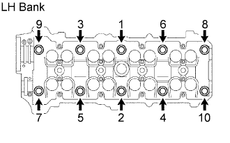
Install and uniformly tighten the 10 cylinder head bolts on one side of the cylinder head in several passes in the sequence shown.
 |
Mark the front of the cylinder head bolt's head with paint.
Tighten the cylinder head bolts another 90° in the sequence shown in the illustration.
Check that the painted mark is now at a 90° angle to the front.
| 25. INSTALL CAMSHAFT (for Bank 2) |
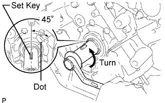 |
Set the crankshaft position.
Using the crankshaft damper bolt, turn the crankshaft, and set the set key of the crankshaft to 45° counterclockwise from the timing mark (1 dot mark) of the oil pump body.
Apply MP grease to the thrust portion of the camshafts.
 |
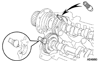
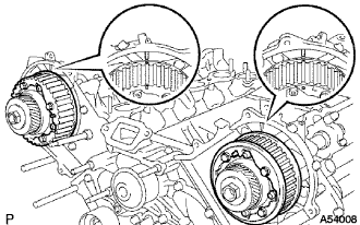
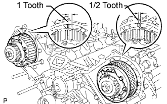
Align the timing marks (1 dot mark each) of the camshaft drive and driven main gears, and place the 2 camshafts.
Set the timing marks (1 dot mark each) of the camshaft drive and driven main gears at an approximately 10° angle.
 |
Apply seal packing to the camshaft housing plug.
Remove the old packing (FIPG) material.
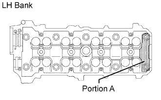
Apply seal packing to the housing plug as shown in the illustration.
 |
Install the camshaft housing plug to the cylinder head as shown in the illustration.
Install the oil control valve filter to the cylinder head.
 |
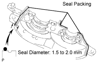
Apply seal packing to the front bearing cap.
Remove any old packing (FIPG) material and be careful not to drop any oil on the contact surfaces of the bearing cap and cylinder head.
Apply seal packing to the bearing cap as shown in the illustration.
 |
Install the front bearing cap.
Install the other bearing caps in the sequence shown, with the arrow mark facing forward.
 |
Push in the camshaft setting oil seal.
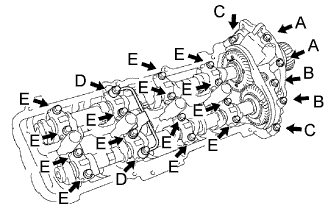 |
Install new seal washers to the bearing cap bolts A and B.
Apply a light coat of engine oil on the threads and under the heads of the bearing cap bolts D and E.
Install the oil feed pipe and the 22 bearing cap bolts as shown in the illustration.
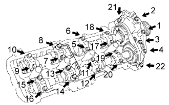 |
Uniformly tighten the 22 bearing cap bolts in several passes in the sequence shown in the illustration.
 |
Remove the service bolt.
| 26. INSTALL NO. 3 CAMSHAFT SUB-ASSEMBLY (for Bank 1) |
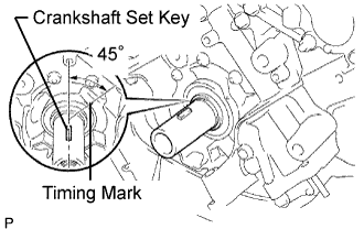 |
Check that the set key of the crankshaft is at a position 45° counterclockwise from the timing mark (1 dot mark) of the oil pump body.
Apply MP grease to the thrust portion of the camshafts.
 |
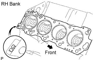
Align the timing marks (2 dot marks each) of the camshaft drive and driven main gears, and place the 2 camshafts.
|
Apply seal packing to the camshaft housing plug.
Remove the old packing (FIPG) material.
Apply seal packing to the housing plug as shown in the illustration.
 |
Install the camshaft housing plug to the cylinder head as shown in the illustration.
Install the oil control valve filter to the cylinder head.
 |
Apply seal packing to the front bearing cap.
Remove any old packing (FIPG) material.
Apply seal packing to the bearing cap as shown in the illustration.
 |
Install the front bearing cap.
Install the other bearing caps in the sequence shown, with the arrow mark facing forward.
 |
Push in the camshaft setting oil seal.
 |
Install new seal washers to the bearing cap bolts A and B.
Apply a light coat of engine oil on the threads and under the heads of the bearing cap bolts D and E.
Install the oil feed pipe and the 22 bearing cap bolts as shown in the illustration.
 |
Uniformly tighten the 22 bearing cap bolts in several passes in the sequence shown in the illustration.
 |
Remove the service bolt.
| 27. INSTALL REAR TIMING BELT PLATE RH |
Install the timing belt plate with the bolt and stud bolt.
| 28. INSTALL REAR NO. 2 TIMING BELT PLATE RH |
Install the timing belt plate with the 2 bolts.
| 29. INSTALL REAR TIMING BELT PLATE LH |
Install the timing belt plate with the bolt.
| 30. INSTALL REAR NO. 2 TIMING BELT PLATE LH |
Install the timing belt plate with the 2 bolts.
| 31. INSTALL CAMSHAFT TIMING PULLEY |
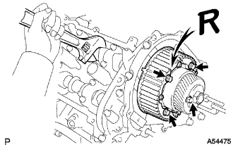 |
Align the knock pin of the camshaft timing tube with the knock pin groove of the timing pulley.
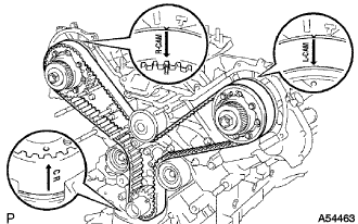
Attach the timing pulley to the camshaft timing tube. Face the timing pulley's "R" mark forward.
Hold the hexagon wrench head portion of the camshaft and install the 4 pulley bolts.
| 32. INSTALL CAMSHAFT TIMING PULLEY SUB-ASSEMBLY LH |
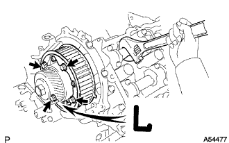 |
Align the camshaft timing tube knock pin with the knock pin groove of the timing pulley.
Attach the timing pulley to the camshaft timing tube. Face the timing pulley's "L" mark forward.
Hold the hexagon wrench head portion of the camshaft and install the 4 pulley bolts.
| 33. INSTALL CRANKSHAFT TIMING PULLEY |
 |
Align the timing pulley set key with the key groove of the pulley.
Using SST and a hammer, tap in the timing pulley, facing the flange side inward.
| 34. INSTALL NO. 2 TIMING BELT IDLER SUB-ASSEMBLY |
Install the idler with the bolt.
Check that the idler moves smoothly.
| 35. INSTALL NO. 1 TIMING BELT IDLER SUB-ASSEMBLY |
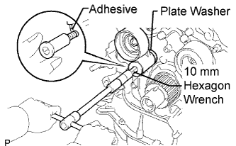 |
Apply adhesive to 2 or 3 threads of the pivot bolt.
Using a 10 mm hexagon wrench, install the plate washer and idler with the pivot bolt.
Check that the idler bracket moves smoothly.
| 36. INSTALL TIMING BELT |
 |
Set the No. 1 cylinder to TDC/compression.
 |
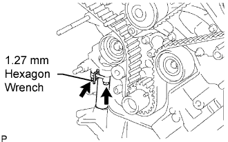
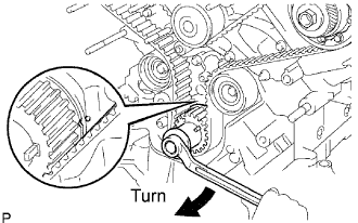
Turn the hexagon wrench head portion of the camshaft to align the timing marks of the camshaft timing pulleys and timing belt plates.
 |
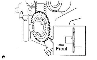
Using the crankshaft damper bolt, turn the crankshaft to align the timing marks of the crankshaft timing pulley and oil pump body.
 |
Install the timing belt.
Remove any oil or water on each pulley, and keep them clean.
Face the front mark (arrow) on the belt forward.
Connect the belt to the crankshaft timing pulley. Align the installation mark of the crankshaft timing pulley.
Connect the belt to the No. 2 idler.
Connect the timing belt to the camshaft timing pulley LH. Align the installation mark on the timing belt with the timing mark of the camshaft timing pulley.
Connect the timing belt to the water pump pulley.
Connect the timing belt to the camshaft timing pulley RH. Align the installation mark on the belt with the timing mark of the camshaft timing pulley.
Connect the timing belt to the No. 1 idler.
 |
Set the belt tensioner.
Using a press, slowly press in the push rod using 981 to 9,807 N (100 to 1,000 kgf, 220 to 2,205 lbf) of pressure.
Align the holes of the push rod and housing. Pass a 1.27 mm hexagon wrench through the holes to keep the setting position of the push rod.
Release the press.
Install the dust boot to the belt tensioner.
 |
Install the belt tensioner.
Temporarily install the belt tensioner with the 2 bolts.
Alternately tighten the 2 bolts.
Using pliers, remove the 1.27 mm hexagon wrench from the belt tensioner.
 |
Check the valve timing.
Using the crankshaft damper bolt, slowly turn the crankshaft timing pulley 2 revolutions from TDC to TDC.
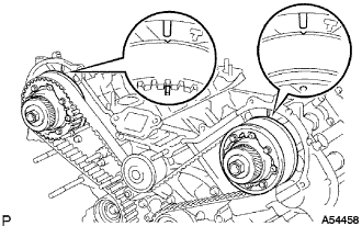 |
Check that each pulley aligns with the timing marks as shown in the illustration.
If the timing marks do not align, remove the belt and reinstall it.
| 37. INSTALL NO. 1 CRANKSHAFT POSITION SENSOR PLATE |
 |
Install the crankshaft position sensor plate as shown in the illustration.
| 38. INSTALL TIMING GEAR COVER SPACER |
Install the gasket to the cover spacer.
Install the cover spacer.
| 39. INSTALL NO. 1 TIMING BELT COVER |
Install the timing belt cover with the 4 bolts.
| 40. INSTALL CRANKSHAFT DAMPER SUB-ASSEMBLY |
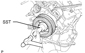 |
Align the damper set key with the key groove of the crankshaft damper.
Using SST and a hammer, tap in the crankshaft damper.
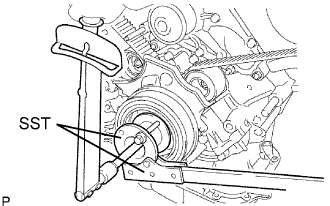 |
Using SST, install the damper bolt.
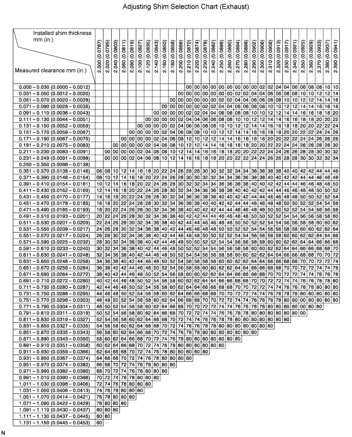
| 41. ADJUST VALVE CLEARANCE |
 |
Using a powerful magnet, remove the valve lifter and adjusting shim.
 |
Determine the replacement adjusting shim size according to these formulas and charts.
Using a micrometer, measure the thickness of the removed shim.
Calculate the thickness of a new shim so that a valve clearance is within the specified value.
T = Thickness of removed shim
A = Measured valve clearance
| Valve | Standard Thickness |
| Intake | T + (A 0.20 mm (0.008 in.)) |
| Exhaust | T + (A 0.30 mm (0.012 in.)) |
Select a new shim with a thickness as close as possible to the calculated value.
Install a new adjusting shim to the spring retainer.
Install the valve lifter.


| Shim No. | Thickness | Shim No. | Thickness | Shim No. | Thickness |
| 00 | 2.000 mm (0.0787 in.) | 28 | 2.280 mm (0.0898 in.) | 56 | 2.560 mm (0.1008 in.) |
| 02 | 2.020 mm (0.0795 in.) | 30 | 2.300 mm (0.0906 in.) | 58 | 2.580 mm (0.1016 in.) |
| 04 | 2.040 mm (0.0803 in.) | 32 | 2.320 mm (0.0913 in.) | 60 | 2.600 mm (0.1024 in.) |
| 06 | 2.060 mm (0.0811 in.) | 34 | 2.340 mm (0.0921 in.) | 62 | 2.620 mm (0.1031 in.) |
| 08 | 2.080 mm (0.0819 in.) | 36 | 2.360 mm (0.0929 in.) | 64 | 2.640 mm (0.1039 in.) |
| 10 | 2.100 mm (0.0827 in.) | 38 | 2.380 mm (0.0937 in.) | 66 | 2.660 mm (0.1047 in.) |
| 12 | 2.120 mm (0.0835 in.) | 40 | 2.400 mm (0.0945 in.) | 68 | 2.680 mm (0.1055 in.) |
| 14 | 2.140 mm (0.0843 in.) | 42 | 2.420 mm (0.0953 in.) | 70 | 2.700 mm (0.1063 in.) |
| 16 | 2.160 mm (0.0850 in.) | 44 | 2.440 mm (0.0961 in.) | 72 | 2.720 mm (0.1071 in.) |
| 18 | 2.180 mm (0.0858 in.) | 46 | 2.460 mm (0.0969 in.) | 74 | 2.740 mm (0.1079 in.) |
| 20 | 2.200 mm (0.0866 in.) | 48 | 2.480 mm (0.0976 in.) | 76 | 2.760 mm (0.1087 in.) |
| 22 | 2.220 mm (0.0874 in.) | 50 | 2.500 mm (0.0984 in.) | 78 | 2.780 mm (0.1094 in.) |
| 24 | 2.240 mm (0.0882 in.) | 52 | 2.520 mm (0.0992 in.) | 80 | 2.800 mm (0.1102 in.) |
| 26 | 2.260 mm (0.0890 in.) | 54 | 2.540 mm (0.1000) in. | ||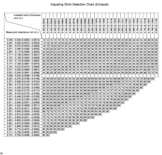
| 42. INSTALL IDLER PULLEY ASSEMBLY |
 |
Install the idler with the 2 bolts and 2 nuts.
| 43. INSTALL V-RIBBED BELT TENSIONER ASSEMBLY |
 |
Install the belt tensioner with the bolt and 2 nuts.
| 44. INSTALL NO. 2 TIMING BELT COVER SUB-ASSEMBLY |
 |
Set the No. 2 cover by matching the claws and pin with each part.
Install the timing belt cover with the 2 bolts.
| 45. INSTALL NO. 2 IDLER PULLEY SUB-ASSEMBLY |
 |
Install the idler pulley and cover plate with the bolt.
| 46. INSTALL SEMICIRCULAR PLUG |
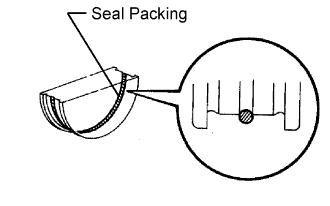 |
Remove any old packing (FIPG) material.
Apply seal packing to the semicircular plug grooves.
 |
Install the 4 semicircular plugs to the cylinder heads as shown in the illustration.
| 47. INSTALL CYLINDER HEAD COVER SUB-ASSEMBLY |
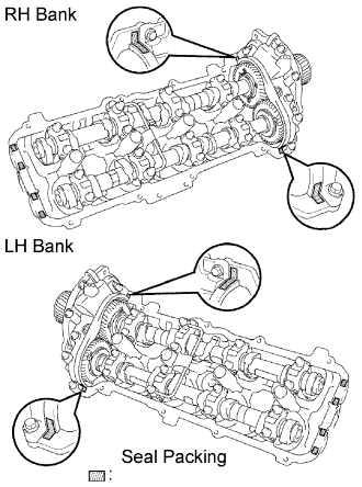 |
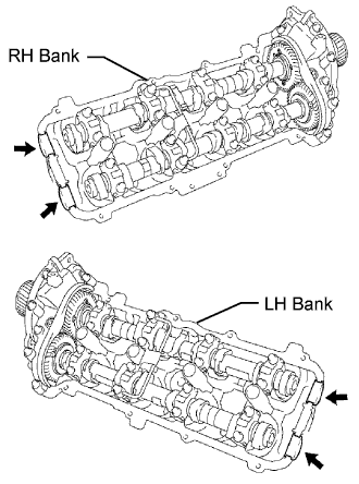
Remove any old packing (FIPG) material.
Apply seal packing to the cylinder heads as shown in the illustration.
Install the gasket to the cylinder head cover.
Install the seal washer to the bolt.
Install the cylinder head cover with the 9 bolts. Uniformly tighten the bolts in several passes.
| 48. INSTALL OIL FILLER CAP HOUSING |
| 49. INSTALL SPARK PLUG |
