CYLINDER HEAD > REMOVAL |
| 1. DISCHARGE FUEL SYSTEM PRESSURE |
Remove the F/PMP fuse.
Remove the engine room No. 2 relay block cover upper.
Remove the F/PMP fuse.
Start the engine.
After the engine has stopped, turn the engine switch off.
Crank the engine again. Check that the engine does not start.
Remove the fuel tank cap to discharge pressure from the fuel tank.
Reinstall the F/PMP fuse.
Disconnect the fuel pump connector.
Remove the rear seat cushion.
Remove the rear floor service hole cover.
Disconnect the fuel pump connector.
Start the engine.
After the engine has stopped, turn the engine switch off.
Crank the engine again. Check that the engine does not start.
Remove the fuel tank cap to discharge pressure from the fuel tank.
Reconnect the fuel pump connector.
Install the rear floor service hole cover.
Install the rear seat.
| 2. DISCONNECT CABLE FROM NEGATIVE BATTERY TERMINAL |
| 3. REMOVE TIMING BELT |
Remove the timing belt (Click here).
| 4. REMOVE IGNITION COIL |
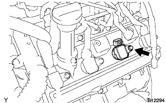 |
Disconnect the ignition coil connector.
Remove the bolt and pull out the ignition coil.
| 5. REMOVE CYLINDER HEAD COVER SUB-ASSEMBLY RH |
 |
Remove the bolt, and disconnect the wire clamp bracket from the camshaft bearing cap.
Remove the bolt, and disconnect the engine wire protector from the cylinder head cover.
Remove the 9 bolts, 9 seal washers and cylinder head cover.
| 6. REMOVE CYLINDER HEAD COVER SUB-ASSEMBLY LH |
 |
Remove the bolt, and disconnect the wire clamp bracket from the camshaft bearing cap.
Remove the 9 bolts, 9 seal washers and cylinder head cover.
| 7. WORK FOR PISTON AND VALVE DAMAGE PREVENTION |
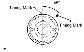 |
Turn the crankshaft timing pulley counterclockwise by 45° and match the timing mark with the illustrated position.
| 8. REMOVE CAMSHAFT TIMING PULLEY |
 |
Hold the crankshaft with a wrench, and remove the 4 bolts and timing pulley.
| 9. REMOVE CAMSHAFT TIMING PULLEY SUB-ASSEMBLY LH |
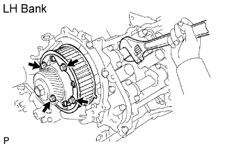 |
Hold the crankshaft with a wrench, and remove the 4 bolts and timing pulley.
| 10. REMOVE REAR NO. 2 TIMING BELT PLATE RH |
Remove the 2 bolts and timing belt plate.
| 11. REMOVE REAR TIMING BELT PLATE RH |
Remove the bolt, stud bolt and timing belt plate.
| 12. REMOVE REAR NO. 2 TIMING BELT PLATE LH |
Remove the 2 bolts and timing belt plate.
| 13. REMOVE REAR TIMING BELT PLATE LH |
Remove the bolt, stud bolt and timing belt plate.
| 14. REMOVE CAMSHAFT TIMING OIL CONTROL VALVE ASSEMBLY RH |
 |
Disconnect the oil control valve connector.
Remove the bolt and oil control valve.
Remove the O-ring from the oil control valve.
| 15. REMOVE CAMSHAFT TIMING OIL CONTROL VALVE ASSEMBLY LH |
 |
Disconnect the oil control valve connector.
Remove the bolt and oil control valve.
Remove the O-ring from the oil control valve.
| 16. REMOVE CAMSHAFT |
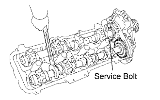 |
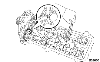
Bring the service bolt hole of the sub gear upward by turning the hexagon head portion of the No. 2 camshaft with a wrench.
Secure the sub gear to the main gear with a service bolt.
| Thread diameter | Thread pinch | Bolt length |
| 6 mm | 1.0 mm | 16 to 20 mm (0.63 to 0.79 in.) |
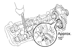 |
Set a wrench to the hexagon head portion of the No. 2 camshaft. Rotate the wrench so that the timing mark (1 dot mark) on the camshaft main gear is moved approximately 10°, as shown in the illustration.
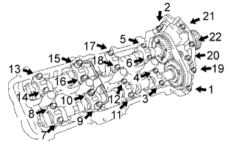 |
Uniformly loosen the 22 bearing cap bolts in several passes in the sequence shown in the illustration.
Remove the 22 bearing cap bolts, 4 seal washers, oil feed pipe, 9 bearing caps, camshaft housing plug, oil control valve filter and 2 camshafts.
| 17. REMOVE NO. 2 CAMSHAFT |
|
Remove the camshafts of the RH bank.
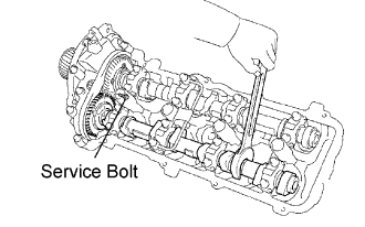
Bring the service bolt hole of the sub gear upward by turning the hexagon head portion of the No. 2 camshaft with a wrench.
Secure the sub gear to the main gear with a service bolt.
| Thread diameter | Thread pinch | Bolt length |
| 6 mm | 1.0 mm | 16 to 20 mm (0.63 to 0.79 in.) |
|
Set a wrench to the hexagon head portion of the No. 2 camshaft. Rotate the wrench so that the timing mark (1 dot mark) on the camshaft main gear is moved approximately 10°, as shown in the illustration.
|
Uniformly loosen the 22 bearing cap bolts in several passes in the sequence shown in the illustration.
Remove the 22 bearing cap bolts, 4 seal washers, oil feed pipe, 9 bearing caps, camshaft housing plug, oil control valve filter and 2 camshafts.
| 18. REMOVE NO. 3 CAMSHAFT SUB-ASSEMBLY |
 |
Bring the service bolt hole of the sub gear upward by turning the hexagon head portion of the exhaust camshaft with a wrench.
Secure the sub gear to the main gear with a service bolt.
| Thread diameter | Thread pinch | Bolt length |
| 6 mm | 1.0 mm | 16 to 20 mm (0.63 to 0.79 in.) |
 |
Set a wrench to the hexagon head portion of the No. 4 camshaft. Rotate the wrench so that the timing marks (2 dot marks each) on the camshaft drive and driven main gears are aligned, as shown in the illustration.
 |
Uniformly loosen the 22 bearing cap bolts in several passes in the sequence shown in the illustration.
Remove the 22 bearing cap bolts, 4 seal washers, oil feed pipe, 9 bearing caps, camshaft housing plug, oil control valve filter and 2 camshafts.
| 19. REMOVE NO. 4 CAMSHAFT SUB-ASSEMBLY |
|
Remove the camshafts of the LH bank.
Bring the service bolt hole of the sub gear upward by turning the hexagon head portion of the exhaust No. 4 camshaft with a wrench.
Secure the sub gear to the main gear with a service bolt.
| Thread diameter | Thread pinch | Bolt length |
| 6 mm | 1.0 mm | 16 to 20 mm (0.63 to 0.79 in.) |
 |
Set a wrench to the hexagon head portion of the No. 4 camshaft. Rotate the wrench so that the timing marks (2 dot marks each) on the camshaft drive and driven main gears are aligned, as shown in the illustration.
|
Uniformly loosen the 22 bearing cap bolts in several passes, in the sequence shown in the illustration.
Remove the 22 bearing cap bolts, 4 seal washers, oil feed pipe, 9 bearing caps, camshaft housing plug, oil control valve filter and 2 camshafts.
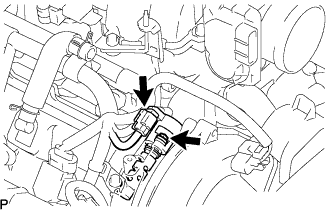
| 20. REMOVE NO. 2 FUEL PIPE SUB-ASSEMBLY |
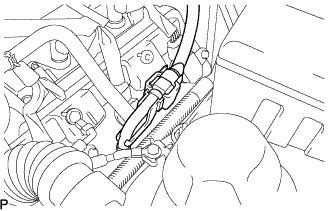 |
Remove the No. 2 fuel pipe clamp.
 |
Disconnect the fuel tube connector connected to the fuel main tube, then pinch and pull the connector.
| 21. REMOVE INTAKE MANIFOLD ASSEMBLY |
Remove the manifold (Click here).
| 22. REMOVE REAR WATER BY-PASS JOINT |
Disconnect the heater inlet hose from the water by-pass joint.
Remove the 4 nuts, water by-pass joint and 2 gaskets.
| 23. REMOVE WATER INLET HOUSING |
Remove the 2 bolts and inlet housing.
| 24. REMOVE FRONT WATER BY-PASS JOINT |
Disconnect the ECT sensor connector.
Remove the 4 nuts, water by-pass joint and 2 gaskets.
| 25. REMOVE FRONT TWC |
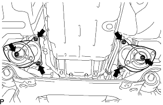 |
Remove the 6 nuts, 2 TWCs and 2 gaskets.
| 26. REMOVE NO. 1 ENGINE HANGER |
 |
Remove the 2 bolts and engine hanger.
| 27. REMOVE NO. 2 ENGINE HANGER |
 |
Remove the 2 bolts and engine hanger.
| 28. REMOVE CYLINDER HEAD SUB-ASSEMBLY |
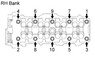 |
Uniformly loosen the 10 cylinder head bolts on the cylinder head in several passes, in the sequence shown. Remove the 10 cylinder head bolts and plate washers.
Remove the cylinder head together with the exhaust manifold.
| 29. REMOVE CYLINDER HEAD GASKET |
| 30. REMOVE NO. 1 EXHAUST MANIFOLD HEAT INSULATOR |
Remove the 4 bolts and heat insulator.
| 31. REMOVE EXHAUST MANIFOLD SUB-ASSEMBLY RH |
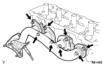 |
Remove the 8 nuts, exhaust manifold and gasket.
| 32. INSPECT EXHAUST MANIFOLD SUB-ASSEMBLY RH |
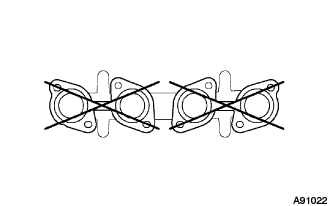 |
Using a precision straightedge and feeler gauge, measure the surface contacting the cylinder head for warpage.
| 33. REMOVE CYLINDER HEAD LH |
 |
Uniformly loosen the 10 cylinder head bolts on the cylinder head in several passes, in the sequence shown in the illustration. Remove the 10 cylinder head bolts and plate washers.
Remove the cylinder head together with the exhaust manifold.
| 34. REMOVE NO. 2 CYLINDER HEAD GASKET |
| 35. REMOVE NO. 2 EXHAUST MANIFOLD HEAT INSULATOR |
Remove the 4 bolts and heat insulator.
| 36. REMOVE EXHAUST MANIFOLD SUB-ASSEMBLY LH |
 |
Remove the 8 nuts, exhaust manifold and gasket.
| 37. INSPECT EXHAUST MANIFOLD SUB-ASSEMBLY LH |
|
Using a precision straightedge and feeler gauge, measure the surface contacting the cylinder head for warpage.
