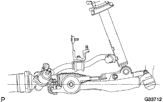
FRONT LOWER BALL JOINT > INSTALLATION |
| 1. INSTALL FRONT LOWER BALL JOINT |
Install the front lower ball joint to the front suspension lower arm with the castle nut.
Install a new clip to the front lower ball joint.
| 2. INSTALL FRONT SUSPENSION LOWER ARM |
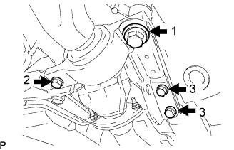 |
Install the front suspension lower arm and side rail plate with the 4 bolts.
 |
Temporarily tighten the bolt, washer and nut.
 |
Install the front lower ball joint with the 2 bolts.
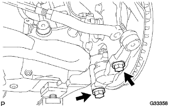
| 3. INSTALL FRONT STABILIZER LINK ASSEMBLY |
 |
Install the front stabilizer link assembly LH with the 2 nuts.
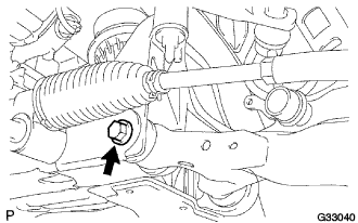
| 4. TEMPORARILY TIGHTEN FRONT SHOCK ABSORBER WITH COIL SPRING |
 |
Fully tighten the bolt on the lower side of the front shock absorber while holding the nut.
| 5. CONNECT TIE ROD ASSEMBLY |
Remove the clip and the castle nut.
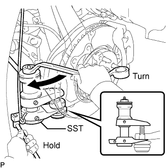 |
Using SST, separate the tie rod end LH from the steering knuckle.
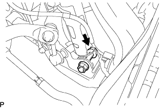
| 6. CONNECT SPEED SENSOR FRONT |
 |
Remove the bolt and separate the speed sensor front from the front shock absorber with coil spring.
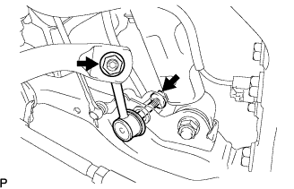
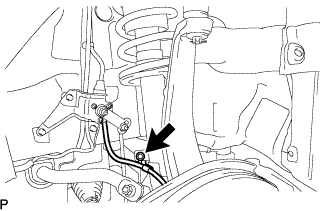
| 7. INSTALL HEIGHT CONTROL SENSOR LINK SUB-ASSEMBLY FRONT |
 |
Remove the nut and separate the front suspension lower arm from the height control sensor link sub-assembly front.
| 8. STABILIZE SUSPENSION |
 |
Install the front wheel.
Lower the vehicle and bounce it up and down several times to stabilize the front suspension.
Remove the front wheel.
Jack up the front suspension lower arm placing a wooden block in between. Apply a load to the front suspension so that the front suspension lower arm is placed in a horizontal position.
| 9. FULLY TIGHTEN FRONT SHOCK ABSORBER WITH COIL SPRING |
|
Fully tighten the bolt on the lower side of the front shock absorber while holding the nut.
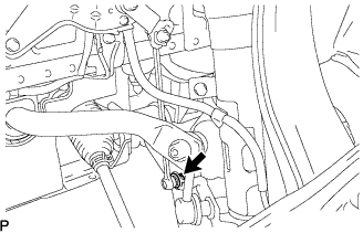
| 10. FULLY TIGHTEN FRONT SUSPENSION LOWER ARM |
|
Fully tighten the bolt on the front of the front suspension lower arm.
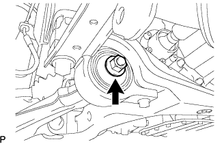 |
Fully tighten the installation nut of the lower arm No.2 bracket sub-assembly.
| 11. INSTALL ENGINE UNDER COVER |
| 12. INSTALL FRONT WHEEL |
| 13. INSPECT AND ADJUST FRONT WHEEL ALIGNMENT |
