INSTRUMENT PANEL SAFETY PAD > REASSEMBLY |
| 1. INSTALL NO. 5 CONSOLE BOX MOUNTING BRACKET |
Install the bracket with the 2 screws.
| 2. INSTALL POWER POINT SOCKET COVER |
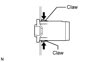 |
Attach the 2 claws to install the socket cover.
| 3. INSTALL POWER OUTLET SOCKET ASSEMBLY |
 |
Align the protrusion on the backside of the socket with the groove of the cover. Then push the socket into the cover.
Connect the connector.
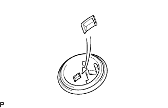
| 4. INSTALL CONSOLE BOX ILLUMINATION LIGHT ASSEMBLY |
 |
Attach the clamp and 2 claws to install the light.
| 5. INSTALL CONSOLE BOX SUB-ASSEMBLY UPPER |
 |
Install the console box, as shown in the illustration.
| 6. INSTALL REAR CONSOLE ARMREST ASSEMBLY |
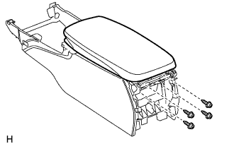 |
Install the armrest with the 4 screws.
| 7. INSTALL ENGINE SWITCH |
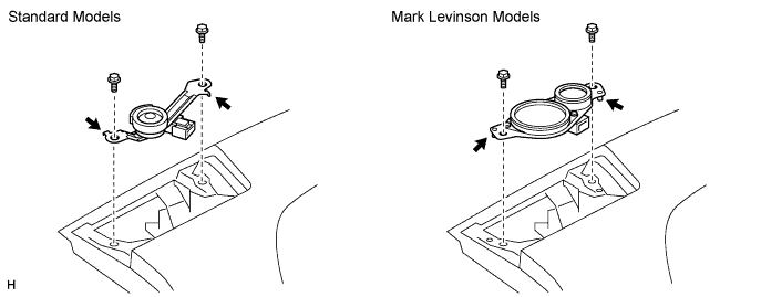
| 8. INSTALL FRONT STEREO COMPONENT SPEAKER |
 |
Temporarily install the speaker by attaching the claws of the speaker to the door panel.
Install the speaker with the 3 screws.
Connect the connector.
| 9. INSTALL NO. 2 FRONT SPEAKER LH |
Connect the connector.
Temporarily install the speaker by aligning the positioning pins of the speaker to the instrument panel.
Install the speaker with the 2 bolts.
| 10. INSTALL NO. 2 FRONT SPEAKER RH |
Connect the connector.
Temporarily install the speaker by aligning the positioning pins of the speaker to the instrument panel.
Install the speaker with the 2 bolts.
| 11. INSTALL NO. 1 SPEAKER HOLE COVER |
 |
Attach the 4 clips to install the speaker panel.
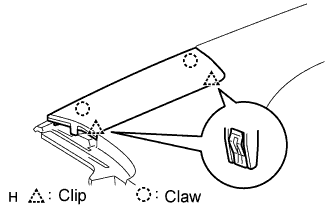
| 12. INSTALL NO. 1 INSTRUMENT PANEL SPEAKER PANEL SUB-ASSEMBLY |
 |
Attach the 2 claws and 2 clips to install the speaker panel.
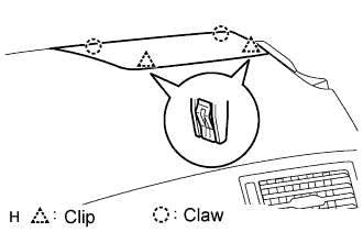
| 13. INSTALL NO. 2 INSTRUMENT PANEL SPEAKER PANEL SUB-ASSEMBLY |
 |
Attach the 2 claws and 2 clips to install the speaker panel.
| 14. INSTALL FRONT PASSENGER AIRBAG ASSEMBLY |
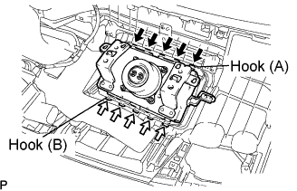 |
Engage the 5 hooks (A).
Engage the 5 hooks (B) and install the front passenger airbag assembly on the instrument panel.
 |
Install the 2 screws.
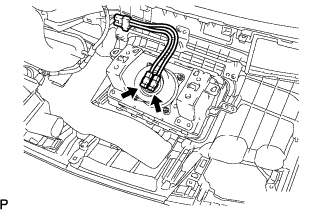 |
Connect the 2 connectors to the front passenger airbag assembly.
| 15. INSTALL NO. 1 INSTRUMENT PANEL REGISTER ASSEMBLY |
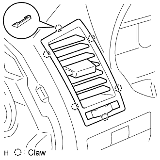 |
Attach the 6 claws to install the register.
| 16. INSTALL NO. 3 INSTRUMENT PANEL REGISTER ASSEMBLY |
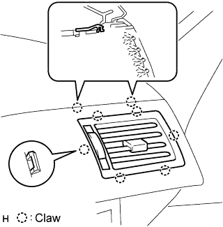 |
Attach the 8 claws to install the register.
| 17. INSTALL NO. 2 INSTRUMENT PANEL REGISTER ASSEMBLY |
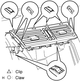 |
Attach the 6 clips and 4 claws to install the register.
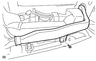
| 18. INSTALL NO. 2 HEATER TO REGISTER DUCT |
 |
Install the duct with the 4 screws.
| 19. INSTALL NO. 1 HEATER TO REGISTER DUCT |
 |
Install the duct with the 3 screws.
| 20. INSTALL NO. 3 HEATER TO REGISTER DUCT |
 |
Install the duct with the 3 screws.
| 21. INSTALL DEFROSTER NOZZLE ASSEMBLY |
 |
Install the duct with the 3 screws.
| 22. INSTALL NO. 2 SIDE DEFROSTER NOZZLE DUCT |
 |
Install the duct with the screw.
| 23. INSTALL NO. 1 SIDE DEFROSTER NOZZLE DUCT |
 |
Install the duct with the screw.
