DTC B1412/12 Ambient Temperature Sensor Circuit |
| DTC No. | DTC Detection Condition | Trouble Area |
| B1412/12 | Open or short in ambient temperature sensor circuit |
|

| 1.READ VALUE OF INTELLIGENT TESTER |
Connect the intelligent tester to the DLC3.
Turn the engine switch on (IG) and push the intelligent tester main switch on.
Select the item below in the Data List, and read the display on the intelligent tester.
| Item | Measurement Item / Display (Range) | Normal Condition | Diagnostic Note |
| Ambient Temp Sensor (Ambi Temp Sens) | Ambient temperature sensor / Min: -23.3°C (-9.94°F) Max: 65.95°C (150.71°F) | Actual ambient temperature is displayed | Open in circuit: -23.3°C (-9.94°F) Short in the circuit: 65.95°C (150.71°F) |
| NG | A |
| OK (Checking from the PROBLEM SYMPTOMS TABLE) | B |
| OK (Checking from the DTC) | C |
|
| ||||
|
| ||||
| A | |
| 2.INSPECT AMBIENT TEMPERATURE SENSOR |
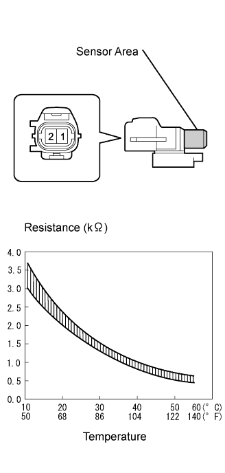 |
Remove the ambient temperature sensor.
Measure the resistance of the sensor.
| Tester Connection | Condition | Specified Condition |
| 1 - 2 | 10°C (50°F) | 3.00 to 3.73 kΩ |
| 1 - 2 | 15°C (59°F) | 2.45 to 2.88 kΩ |
| 1 - 2 | 20°C (68°F) | 1.95 to 2.30 kΩ |
| 1 - 2 | 25°C (77°F) | 1.60 to 1.80 kΩ |
| 1 - 2 | 30°C (86°F) | 1.28 to 1.47 kΩ |
| 1 - 2 | 35°C (95°F) | 1.00 to 1.22 kΩ |
| 1 - 2 | 40°C (104°F) | 0.80 to 1.00 kΩ |
| 1 - 2 | 45°C (113°F) | 0.65 to 0.85 kΩ |
| 1 - 2 | 50°C (122°F) | 0.50 to 0.70 kΩ |
| 1 - 2 | 55°C (131°F) | 0.44 to 0.60 kΩ |
| 1 - 2 | 60°C (140°F) | 0.36 to 0.50 kΩ |
|
| ||||
| OK | |
| 3.CHECK WIRE HARNESS (AMBIENT TEMPERATURE SENSOR - ECM) |
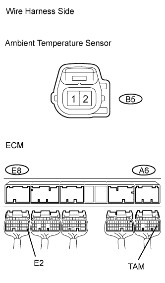 |
3UZ-FE
Disconnect the B5 ambient temperature sensor connector.
Disconnect the A6 and E8 ECM connectors .
Measure the resistance of the wire harness side connectors.
| Tester Connection | Condition | Specified Condition |
| B5-1 - A6-18 (TAM) | Always | Below 1 Ω |
| B5-2 - E8-28 (E2) | Always | Below 1 Ω |
| A6-18 (TAM) - Body ground | Always | 10 kΩ or higher |
| E8-28 (E2) - Body ground | Always | 10 kΩ or higher |
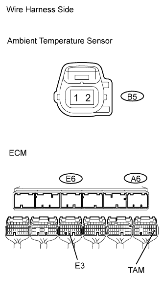 |
3GR-FE, 3GR-FSE
Disconnect the B5 ambient temperature sensor connector.
Disconnect the A6 and E6 ECM connectors.
Measure the resistance of the wire harness side connectors.
| Tester Connection | Condition | Specified Condition |
| B5-1 - A6-18 (TAM) | Always | Below 1 Ω |
| B5-2 - E6-30 (E3) | Always | Below 1 Ω |
| A6-18 (TAM) - Body ground | Always | 10 kΩ or higher |
| E6-30 (E3) - Body ground | Always | 10 kΩ or higher |
|
| ||||
| OK | ||
| ||
